


 Home /
How Do I Select the Right Gearbox Ratio?

Right Angle Geared Motor: Matching Electrical Supply, Variable Speed and Braking
Oct 26, 2026

Planning a Bevel Reducer Installation: Turn Shaft Requirements Into a Practical Drive Layout
Oct 26, 2026

Choosing an Overhead Crane Gearbox by Its Hoisting or Travel Function
Oct 26, 2026

Replacing an Industrial Worm Gearbox: What to Keep and What to Reassess
Oct 25, 2026
To select the right gearbox ratio, divide the motor’s actual input speed by the required gearbox output speed. Then choose the nearest available ratio and verify that the resulting output torque, efficiency, service factor, duty cycle and gearbox rating suit the application. For high reductions, also determine whether the ratio should be divided across multiple stages.
What Does a Gearbox Ratio Mean?
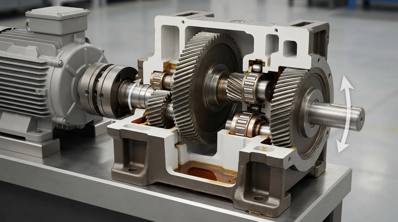
A gearbox ratio compares the speed of the input shaft with the speed of the output shaft. A 20:1 ratio means the input shaft turns 20 times for one output-shaft rotation, subject to the gearbox’s operating conditions and efficiency.
A reduction gearbox decreases output speed while increasing theoretical torque multiplication. However, the ratio alone does not determine whether a gearbox is suitable. The gearbox must also meet the machine’s torque, duty-cycle, shaft-load, mounting and environmental requirements.
| Term | Meaning | Why it matters |
|---|---|---|
| Input speed | Motor or gearbox input speed, normally in revolutions per minute (RPM) | Starting value for the ratio calculation |
| Output speed | Required speed at the driven machine shaft | Determines the reduction required |
| Gearbox ratio | Input speed divided by output speed | Identifies the approximate reduction |
| Output torque | Torque available at the gearbox output shaft | Must meet the machine load after efficiency and service-factor checks |
What Is the Gearbox Ratio Formula?
The gearbox ratio formula is:
Required gearbox ratio = motor input speed ÷ required output speed
Use the same speed unit on both sides of the equation, normally RPM. The result is expressed as a ratio such as 25:1.
According to Industrial Gearbox Supply, a motor input speed of 1,750 RPM and a required output speed of 70 RPM produce a calculated ratio of 25:1. The calculation is:
1,750 RPM ÷ 70 RPM = 25
Use the motor’s actual operating speed where possible. Nameplate or synchronous speed can provide a starting reference, but actual speed under the intended electrical and load conditions gives a more realistic output-speed estimate.
Basic ratio-selection process
- Identify the motor’s actual operating speed.
- Identify the required output speed at the driven machine.
- Divide input RPM by output RPM.
- Compare the calculated ratio with available standard ratios.
- Recalculate the actual output speed using the selected ratio.
- Verify output torque, efficiency, service factor, duty cycle and gearbox ratings.
A tooth-count calculation can also determine the ratio of individual gears, but motor speed divided by required output speed is the more direct method for selecting an industrial motor–gearbox combination.
What Information Do I Need Before Selecting a Ratio?
Before selecting a gearbox ratio, collect the motor speed, required output speed, required torque, duty cycle, load pattern, mounting details and environmental conditions. Selecting a ratio from speed alone can produce a gearbox that runs at the correct speed but cannot handle the application.
Gather the following information:
- Motor power and actual operating speed
- Required continuous and peak output torque
- Required output speed or speed range
- Operating hours and duty cycle
- Starts per hour
- Reversing frequency
- Shock, impact or variable-load conditions
- Radial and axial loads on the output shaft
- Mounting orientation and shaft arrangement
- Ambient temperature, dust, moisture and contamination
- Available installation space
- Required mounting dimensions and connection details
Duty cycle describes how long and how often the gearbox operates. A gearbox used continuously may require a different rating from one used intermittently, even when both applications use the same output speed.
For the broader equipment-selection process, see this guide to choosing an industrial gearbox.
How Do I Select the Ratio Step by Step?
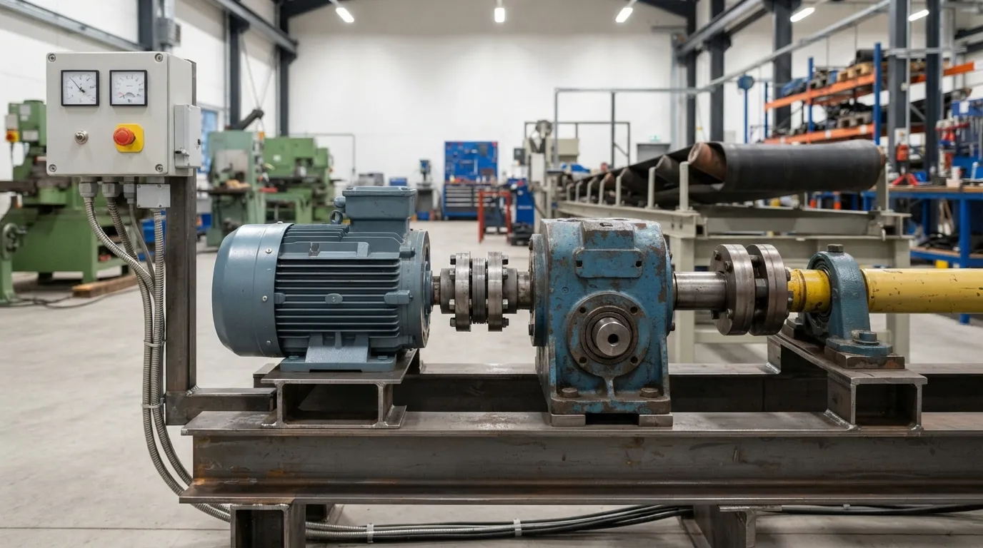
To select a gearbox ratio, calculate the ideal reduction from the two shaft speeds, compare it with available ratios, then validate torque and mechanical suitability. The following process separates the speed calculation from the final gearbox-sizing decision.
1. Determine the required output speed
Start with the shaft speed required by the driven machine. For a conveyor, mixer, packaging machine or other industrial drive, use the machine’s required operating speed rather than an assumed catalogue value.
If the machine can operate across a speed range, calculate the ratio for the important operating points and identify whether a fixed-ratio gearbox is suitable.
2. Confirm the motor’s actual input speed
Use the motor’s actual operating speed when it is known. Motor speed may differ from a nominal or synchronous value under real operating conditions.
If the motor runs at a different speed from the value used in the calculation, the gearbox output speed will also change.
3. Calculate the ideal ratio
Divide motor input speed by required output speed:
Ideal ratio = motor input speed ÷ required output speed
The result is the target reduction, not necessarily the exact ratio that will be available from a gearbox manufacturer.
4. Compare available standard ratios
Gearboxes are commonly offered in a range of standard ratios. Select a candidate ratio close to the calculated value, then determine its actual output speed:
Actual output speed = motor input speed ÷ selected gearbox ratio
A slightly different standard ratio may be acceptable if the resulting machine speed remains within the application’s operating limits.
5. Check output torque
Calculate or verify the output torque available from the selected motor and gearbox. The result must meet the machine’s required torque after accounting for gearbox efficiency and application conditions.
6. Apply the service factor
Service factor accounts for conditions such as shock loads, frequent starts and stops, reversing loads and long duty cycles. These conditions can require a higher gearbox rating than a smooth, continuous load.
7. Check the complete gearbox specification
Confirm the gearbox’s torque rating, shaft-load capacity, mounting arrangement, environmental suitability and physical fit. Ratio selection is complete only when these checks also pass.
8. Decide whether multiple stages are appropriate
If the total reduction is high or a suitable single-stage ratio is unavailable, compare single-stage and multi-stage arrangements. The decision should consider efficiency, torque, size, stage ratings and the available gearbox design.
| Selection step | Input required | Result or decision |
|---|---|---|
| Speed calculation | Motor RPM and required output RPM | Ideal ratio |
| Standard-ratio review | Ideal ratio and available ratios | Candidate gearbox ratio |
| Torque check | Motor torque, ratio and efficiency | Estimated output torque |
| Service-factor check | Load and operating conditions | Required rated torque |
| Mechanical check | Shaft loads, mounting and environment | Suitable gearbox configuration |
| Stage check | Total reduction and gearbox architecture | Single-stage or multi-stage choice |
Worked Example: Calculating a Gearbox Ratio
If a motor operates at 1,750 RPM and the machine requires 70 RPM at the gearbox output, the calculated ratio is 25:1. That result identifies the approximate reduction, but torque, efficiency, service factor and the nearest available ratio still need to be checked.
| Item | Value | Calculation or implication |
|---|---|---|
| Motor input speed | 1,750 RPM | Input to the ratio formula |
| Required output speed | 70 RPM | Target gearbox output |
| Ideal ratio | 25:1 | 1,750 ÷ 70 |
| Candidate gearbox ratio | Nearest available value | Recalculate actual output RPM |
| Final approval | Not determined by ratio alone | Check torque, service factor and rating |
According to Industrial Gearbox Supply, 1,750 RPM divided by 70 RPM produces a 25:1 ratio. The example does not mean that 25:1 is suitable for every machine. It is correct only for those stated speed inputs, and the final selection depends on the load and gearbox rating.
If the nearest available gearbox ratio were different from 25:1, calculate the actual output speed using that ratio. Then confirm whether the speed difference is acceptable before checking torque and duty conditions.
How Do I Check Output Torque After Calculating the Ratio?
Estimate gearbox output torque from motor torque, selected ratio and gearbox efficiency, then compare the result with the required application torque after applying the appropriate service factor. A gearbox with the correct speed ratio can still be undersized for the load.
A simplified relationship is:
Estimated output torque = motor torque × selected ratio × gearbox efficiency
Industrial Gearbox Supply explains that increasing the ratio increases output torque but also increases loading on gears and bearings. The selected gearbox therefore needs sufficient rated torque, not merely the correct numerical ratio.
Haydon Kerk Pittman provides an illustrative calculation using 26 ounce-inches of motor torque, a 75.1:1 ratio and 73% gearbox efficiency:
26 oz-in × 75.1 × 0.73 = approximately 1,425 oz-in
That example uses the stated motor, ratio and efficiency values. The 73% figure should not be treated as a universal efficiency assumption for every gearbox type or application.
For a deeper load review, see industrial gearbox torque sizing. The torque check should include continuous load, starting load and any peak or shock condition that the gearbox will experience.
How Does Service Factor Affect Gearbox Ratio Selection?
Service factor increases the required gearbox rating when operating conditions are more demanding than a smooth, steady load. Shock loads, frequent starts and stops, reversing and long duty cycles can all affect the required rating even when the speed ratio is correct.
Industrial Gearbox Supply describes the calculation concept as:
Required rated torque = calculated application torque × service factor
The correct service factor depends on the application and the gearbox manufacturer’s sizing method. Do not insert a generic value without considering the actual load pattern.
Ask whether the machine has:
- Continuous operation
- High starting torque
- Frequent starts and stops
- Reversing operation
- Impact or shock loads
- Variable load
- Long daily operating hours
Service factor is not a substitute for checking the gearbox’s actual torque, radial-load and axial-load ratings. It is one part of the final sizing process.
For the relationship between motor speed, torque and reduction, see this guide to gear motor torque speed calculation.
When Should I Split the Ratio Across Multiple Gearbox Stages?
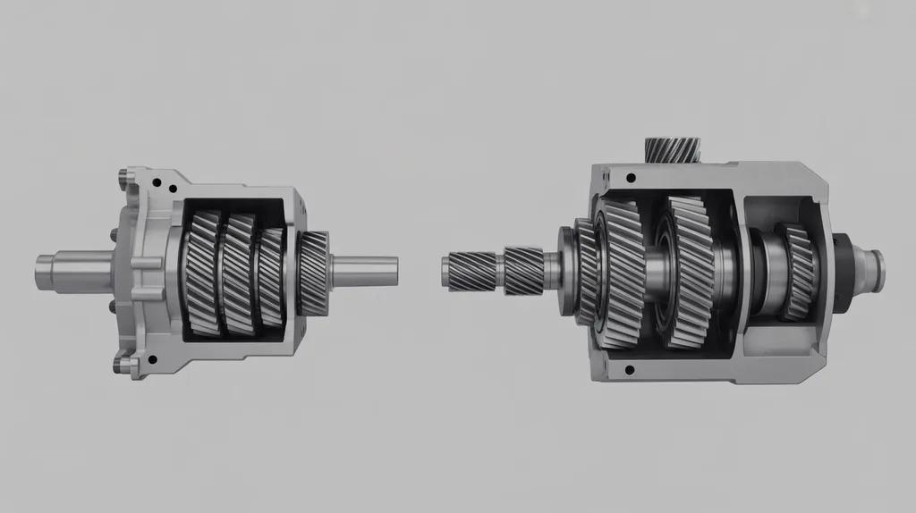
Split a high total reduction across multiple stages when the required ratio is too large, inefficient or mechanically unsuitable for a single reduction stage. The correct stage arrangement depends on the required torque, output speed, efficiency, gearbox size, available ratios and manufacturer’s design limits.
A total reduction can be represented as the product of individual stage ratios. For example, a total reduction can be divided between two stages rather than asking one stage to provide the entire reduction. The individual stage values must still be checked for torque, efficiency and mechanical loading.
There is no universal ratio threshold at which every application must change from one stage to multiple stages. The decision should be based on the gearbox design and the complete application specification.
| Consideration | One-stage reduction | Multi-stage reduction |
|---|---|---|
| Total reduction | Suitable when an appropriate single-stage design is available | Divided among multiple reductions |
| Physical design | May be simpler where the design is suitable | May increase component count and packaging requirements |
| Efficiency | Check the selected stage’s actual efficiency | Check combined efficiency across stages |
| Torque and loading | Check gear and bearing ratings | Check each stage and the final output rating |
| Selection method | Compare available single-stage ratios | Compare total ratio and stage combinations |
| Decision basis | Manufacturer limits and application data | Manufacturer limits, application data and stage arrangement |
For a more detailed comparison, see single stage vs multi stage gearbox.
How Do I Choose a Gearbox Type After Determining the Ratio?
After calculating the ratio, choose the gearbox type by considering torque, efficiency, duty cycle, mounting, shaft loads, space, environment and operating requirements. Helical, worm, planetary and other gearbox designs should be compared by application fit rather than ratio alone.
| Gearbox type | Selection question | Avoid assuming |
|---|---|---|
| Helical | Is the required ratio, torque and mounting arrangement available? | Do not assume one design is universally most efficient |
| Worm | Are the speed, duty cycle, thermal and efficiency requirements compatible? | Do not assume it is automatically the best choice for every application |
| Planetary | Is compact, high-torque reduction relevant to the application? | Do not assume a particular capacity or ratio without product evidence |
| Heavy-duty industrial reducer | Are the load, shock, duty and installation demands high? | Do not claim a capacity without a verified rating |
Mingye supplies several industrial power-transmission categories, including R, S, K and F series helical gear motors, HB series heavy-duty industrial gearboxes, heavy-duty planetary reducers, NMRV worm gear motors, cycloidal reducers and cylindrical gear reducers. The appropriate product family still depends on the application data.
For a focused discussion of high-ratio planetary designs, see planetary gearbox ratio.
What Are the Most Common Gearbox Ratio Selection Mistakes?
Common mistakes include using the wrong motor speed, selecting from output speed alone, ignoring efficiency, omitting service factor and assuming that the nearest catalogue ratio is automatically suitable. Ratio selection must be followed by torque, load and mechanical-fit checks.
Use this inspection list before approving a gearbox:
- Using synchronous speed instead of actual operating speed
- Confusing motor speed with required machine output speed
- Treating the calculated ratio as the final gearbox selection
- Ignoring efficiency when estimating output torque
- Applying no service factor to shock or intermittent loads
- Failing to check starts, stops and reversing
- Ignoring radial or axial shaft loads
- Selecting a ratio without checking the available standard ratio
- Choosing one stage when the required reduction may need multiple stages
- Ignoring mounting orientation, heat or contamination
- Assuming that a higher ratio is automatically better
- Selecting a gearbox without checking the driven machine’s actual torque
What Should I Send to a Gearbox Supplier for a Final Recommendation?
Send the supplier the motor speed, required output speed, torque, duty cycle, load pattern, starts and stops, shock or reversing conditions, mounting arrangement, shaft loads, environment and available space. This information allows the supplier to check the ratio and gearbox size together.
A useful specification request includes:
- Motor power and actual operating speed
- Required output speed or speed range
- Continuous and peak torque
- Duty cycle and operating hours
- Starts per hour and reversing frequency
- Shock, impact or variable-load conditions
- Radial and axial loads
- Mounting position and shaft orientation
- Ambient temperature, dust, moisture and contamination
- Required mounting dimensions and transmission ratio
- Available space and connection details
Mingye designs and manufactures both motors and reducers in its own CNC-equipped factory using modular, standardized designs. Its product range includes industrial gear motors, heavy-duty gearboxes and specialized reducers, and its OEM service includes customization of mounting dimensions and transmission ratios.
OEM readers can also review this gear reduction motor buying guide for oems when preparing a complete equipment specification.
Frequently Asked Questions
What If the Exact Gearbox Ratio I Calculate Is Not Available?
Select the nearest available ratio, calculate its actual output speed and confirm that the resulting speed remains acceptable for the machine. Then verify output torque, efficiency, service factor, duty cycle and gearbox rating. If the difference is unacceptable, compare another ratio, motor speed or multi-stage arrangement instead of forcing an unsuitable selection.
Does a Higher Gearbox Ratio Always Provide More Useful Torque?
A higher reduction ratio generally increases theoretical torque multiplication and decreases output speed, but the usable result depends on motor torque, gearbox efficiency, service factor and rated capacity. A higher ratio is not automatically better if it produces the wrong output speed or exceeds gear, bearing or thermal limits.
Should I Use Motor Nameplate Speed or Actual Operating Speed?
Use the motor’s actual operating speed when it is known under the intended electrical and load conditions. Nameplate or synchronous speed can provide a starting reference, but the final ratio calculation should reflect the speed the motor and gearbox will actually experience. This produces a more realistic output-speed estimate.
Is Gearbox Ratio Selection the Same as Gearbox Sizing?
No. Ratio selection establishes the approximate speed reduction, while gearbox sizing also checks output torque, efficiency, service factor, duty cycle, shaft loads, mounting, environment and physical fit. A gearbox can have the correct numerical ratio and still be unsuitable if its torque or mechanical ratings do not meet the application.
Share on Social:


Contact Us
In This Article
Right Angle Geared Motor: Matching Electrical Supply, Variable Speed and Braking
Oct 26, 2026
Planning a Bevel Reducer Installation: Turn Shaft Requirements Into a Practical Drive Layout
Oct 26, 2026
Choosing an Overhead Crane Gearbox by Its Hoisting or Travel Function
Oct 26, 2026
Replacing an Industrial Worm Gearbox: What to Keep and What to Reassess
Oct 25, 2026