


 Home /
How to Size an Industrial Gearbox for Torque?

Right Angle Geared Motor: Matching Electrical Supply, Variable Speed and Braking
Oct 26, 2026

Planning a Bevel Reducer Installation: Turn Shaft Requirements Into a Practical Drive Layout
Oct 26, 2026

Choosing an Overhead Crane Gearbox by Its Hoisting or Travel Function
Oct 26, 2026

Replacing an Industrial Worm Gearbox: What to Keep and What to Reassess
Oct 25, 2026
To size an industrial gearbox for torque, calculate the required output torque, multiply it by the appropriate service factor, and confirm that the result does not exceed the gearbox’s rated torque. Then check start-up and peak torque, thermal capacity, speed ratio, duty cycle, and radial or axial shaft loads before selecting the gearbox frame and configuration.
What Does Gearbox Torque Sizing Mean?
Gearbox torque sizing is the process of matching a driven machine’s required output torque and speed with a gearbox that can safely handle its operating conditions. The selected gearbox must satisfy continuous torque, starting torque, peak torque, thermal, and shaft-load requirements.
Torque is the rotational force transmitted through a shaft, normally expressed in newton-metres (Nm). Rated output torque is the torque capacity stated for a gearbox under specified operating conditions. The rating may depend on speed, duty cycle, service factor, temperature, lubrication, and other catalogue conditions.
A gearbox can pass a continuous-torque calculation and still be unsuitable if:
- The machine requires excessive breakaway torque.
- Acceleration creates a high transient load.
- The gearbox operates continuously at low speed and exceeds its thermal capacity.
- A pulley, sprocket, drum, or other component creates excessive overhung or radial load.
- Frequent starts, reversals, jams, or shock loads exceed the permissible peak torque.
STOBER distinguishes between nominal, acceleration, and peak torque when selecting a gearbox. Power Motor also identifies speed, ratio, load cycle, starting conditions, radial loads, axial loads, and environment as relevant application data.
What Information Do You Need Before Sizing an Industrial Gearbox?
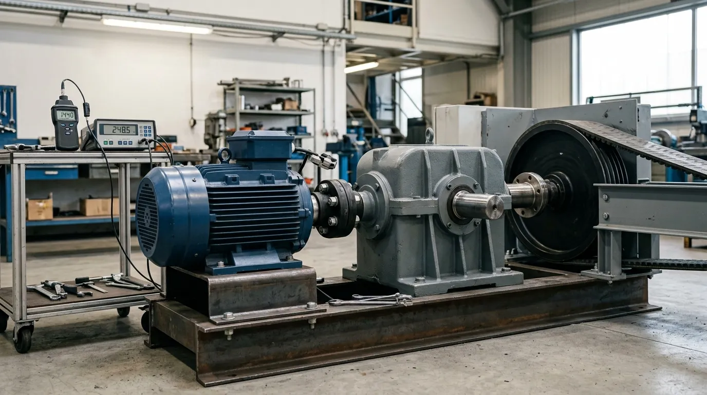
Before calculating torque, collect the complete operating profile. Motor power alone is not enough because torque depends on speed, ratio, efficiency, load behavior, and duty cycle.
| Input | Unit or description | Why it matters |
|---|---|---|
| Motor power or input torque | Kilowatts or Nm | Establishes available drive torque |
| Input speed | Revolutions per minute (rpm) | Used to calculate ratio and motor torque |
| Required output speed | rpm | Determines the reduction ratio |
| Continuous load torque | Nm | Sets the normal running requirement |
| Start-up and peak torque | Nm | Checks short-duration capacity |
| Duty cycle | Runtime, starts per hour, reversals | Determines service severity and thermal load |
| Inertia and acceleration time | Application-specific | Determines acceleration torque |
| Radial or axial shaft loads | Newtons and load position | Checks shaft and bearing capacity |
| Mounting and environment | Position, temperature, dust, moisture | Affects lubrication and thermal performance |
Also record:
- Whether the load is uniform, variable, or shock-loaded.
- The number of starts and stops per hour.
- The number and frequency of reversals.
- The required operating life.
- Whether the motor is controlled by a variable frequency drive.
- The location of pulleys, sprockets, drums, or pinions relative to the gearbox bearing.
- The available mounting space and shaft arrangement.
For a broader selection process covering ratio, mounting, duty, and gearbox type, see this guide to choosing an industrial gearbox.
How Do You Calculate Gearbox Ratio and Output Torque?
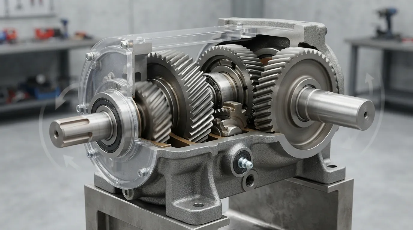
Calculate the required ratio by dividing input speed by required output speed. Then calculate output torque from power and output speed, or estimate it from motor torque multiplied by ratio and gearbox efficiency.
1. Calculate the required ratio
\[ i=\frac{n\text{input}}{n\text{output}} \]
Where:
- \(i\) = reduction ratio
- \(n_\text{input}\) = gearbox input speed in rpm
- \(n_\text{output}\) = required gearbox output speed in rpm
For example, Guomao shows a 1,470 rpm input speed and a 49 rpm output speed as approximately a 30:1 ratio:
\[ i=\frac{1,470}{49}=30 \]
The selected catalogue ratio may be a nearby standard value rather than exactly 30:1. The final output speed should be checked against the actual motor speed, slip, drive frequency, and gearbox ratio.
2. Calculate output torque from power
When power is in kilowatts and speed is in rpm:
\[ T=\frac{9,550 \times P}{n} \]
Where:
- \(T\) = torque in Nm
- \(P\) = power in kilowatts
- \(n\) = shaft speed in rpm
If the power value is motor input power, account for gearbox efficiency before treating the result as available output torque.
3. Estimate torque from motor torque and ratio
A second approximation is:
\[ T\text{output}\approx T\text{motor}\times i\times\eta \]
Where:
- \(T_\text{motor}\) = motor input torque
- \(i\) = reduction ratio
- \(\eta\) = gearbox efficiency as a decimal
This relationship shows why a reduction gearbox can increase output torque while reducing output speed. It does not mean that every gearbox can transmit unlimited torque at a higher ratio. The gearbox’s own rated torque, thermal rating, bearings, shafts, and duty limits still control the selection.
How Should Service Factor and Load Class Affect Gearbox Sizing?
Apply the service factor or duty adjustment specified by the gearbox manufacturer to the required continuous torque. The service-factor-adjusted torque must remain within the gearbox’s applicable rated torque, while starting and peak torque must be checked separately.
A service factor is an adjustment used to account for operating severity, such as shock, starts, reversals, runtime, or variable loading. The correct value depends on the application and the gearbox manufacturer’s selection table; there is no universal service-factor value for every machine.
| Load condition | Sizing implication |
|---|---|
| Uniform, steady operation | Lower severity than frequent shock or reversal duty, subject to catalogue guidance |
| Moderate load variation | Requires an application-specific service adjustment |
| Frequent starts and stops | Increases acceleration and thermal demand |
| Frequent reversals | Requires peak-torque and fatigue-related checks |
| High inertia | May create substantial acceleration torque |
| Shock, jams, or impact | Requires separate peak or emergency-stop verification |
| High ambient temperature | May reduce usable thermal capacity |
| Continuous low-speed operation | Requires thermal and lubrication review |
Use the following basic check:
\[ T\text{design}=T\text{continuous}\times S \]
Where:
- \(T_\text{design}\) = service-factor-adjusted torque
- \(T_\text{continuous}\) = normal operating torque
- \(S\) = applicable service factor
The result must not exceed the relevant gearbox rated torque. However, service factor is not a replacement for calculating a real peak load.
STOBER notes that gearbox selection can require repeated derating for service factor, cycles per hour, expected life, and operating temperature. Its guide states that the combined derating can exceed a factor of five in some cases. Treat that as application guidance, not as a universal design value.
How Do You Check Starting, Acceleration, Peak, and Emergency-Stop Torque?
Treat continuous, breakaway, acceleration, peak, and emergency-stop torque as separate requirements. A gearbox that passes the normal running-torque calculation can still fail during starting, rapid acceleration, reversal, jamming, or emergency stopping.
| Torque condition | What to calculate or obtain | What to compare |
|---|---|---|
| Continuous running | Normal driven-load torque | Continuous or nominal gearbox rating |
| Breakaway or start-up | Static friction and initial load | Starting or acceleration capacity |
| Acceleration | Inertia, speed change, and acceleration time | Acceleration torque rating |
| Peak process load | Short-duration maximum torque | Peak torque rating |
| Emergency stop or jam | Worst credible transient | Emergency or permissible peak rating |
Use this process:
- Identify the highest normal operating torque.
- Determine breakaway or starting torque.
- Calculate acceleration torque from inertia, speed change, and acceleration time.
- Identify reversals, jams, impact events, and emergency stops.
- Obtain the allowable duration and frequency for each gearbox peak rating.
- Compare every transient value with the relevant catalogue rating.
Makikawa Motion states that a load profile should distinguish nominal, peak, and emergency-stop torque. Its examples describe peak loads of 2–5 times nominal torque for applications such as conveyor start-stop cycles or robotic reversals. That range is an example from the source, not a universal design factor.
Power Motor also notes that starting friction and acceleration require separate checks from continuous torque. If the machine’s peak torque is unknown, measure it, calculate it from the application, or provide the full load profile to the gearbox manufacturer.
How Do Thermal Limits Affect Gearbox Torque Sizing?
Thermal sizing verifies that the gearbox can dissipate heat during the complete duty cycle. A gearbox may have sufficient mechanical torque capacity but still be unsuitable if continuous operation, low output speed, frequent starts, high ambient temperature, or limited cooling causes excessive temperature.
Gearbox efficiency losses become heat. The amount of heat depends on transmitted power, efficiency, operating time, speed, lubrication, enclosure, ambient temperature, and cooling conditions.
Review these thermal inputs:
- Continuous operating hours.
- Starts and stops per hour.
- Reversals per hour.
- Output speed and reduction ratio.
- Ambient temperature.
- Mounting orientation.
- Ventilation or cooling conditions.
- Lubricant and lubrication method.
- Catalogue thermal rating at the selected duty.
A thermal check is especially important when:
- The gearbox runs continuously.
- The output speed is low.
- The reduction ratio is high.
- The gearbox operates in a hot or enclosed location.
- The application has frequent starts and stops.
- The machine operates close to the gearbox’s mechanical torque rating.
If the mechanical torque check passes but the thermal rating does not, the solution may require a different gearbox size, ratio, cooling arrangement, duty profile, or mounting configuration. The correct change must come from the relevant manufacturer data rather than from torque alone.
How Do You Check Overhung, Radial, and Axial Loads?
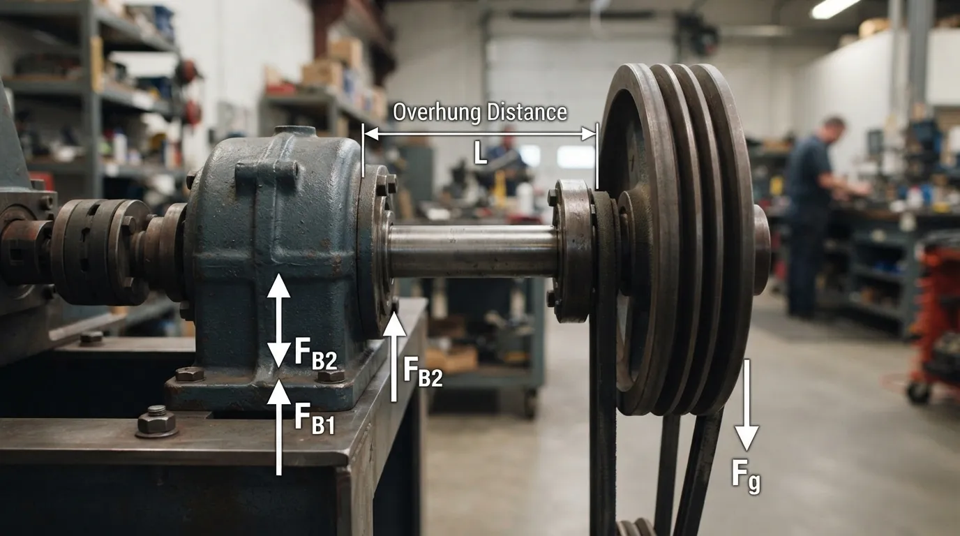
Check the force and position of every pulley, sprocket, pinion, drum, roller, or other component mounted on or coupled to the gearbox shaft. Torque compliance alone does not confirm that the gearbox shaft and bearings can withstand external loads.
An overhung load is a force applied away from the gearbox bearing, creating a bending moment on the shaft and bearing. Radial load acts perpendicular to the shaft, while axial load acts along the shaft.
| Item | Required information |
|---|---|
| Mounted component | Pulley, sprocket, drum, pinion, coupling, or roller |
| Force direction | Radial, axial, or combined |
| Force magnitude | Newtons |
| Load position | Distance from gearbox bearing or shaft shoulder |
| Load cycle | Continuous, intermittent, reversing, or impact |
| Catalogue limit | Permissible radial or axial load at the relevant speed and position |
Makikawa Motion specifically identifies pulleys, sprockets, pinions, cable drums, and rollers as possible sources of radial and axial forces. The load must be compared with the gearbox’s shaft and bearing limits at the actual speed and load position.
Do not approve a gearbox from torque and ratio alone when an external component is mounted directly to the shaft. A coupling or different shaft arrangement may reduce external loading, but the design still requires verification.
[DIAGRAM: Industrial gearbox output shaft with a pulley or sprocket, showing radial force, axial force, overhung distance, and the bearing reference point.]
Worked Example: Sizing a Gearbox for Continuous and Peak Torque
A worked example should calculate output speed and continuous torque, apply a stated service factor, and then compare the peak requirement with the gearbox’s permissible peak capacity. The figures below illustrate the method only and do not represent a universal gearbox rating.
Example application data
- Motor power: 5.5 kW
- Motor input speed: 1,470 rpm
- Required output speed: 49 rpm
- Illustrative gearbox efficiency: 94%
- Illustrative service factor: 1.5
- Illustrative measured process peak: 2,000 Nm
The efficiency and service factor are hypothetical values for demonstrating the calculation. The actual figures must come from the selected gearbox catalogue and application conditions.
Step 1: Calculate the ratio
\[ i=\frac{1,470}{49}=30:1 \]
The application therefore requires approximately a 30:1 reduction.
Step 2: Calculate ideal output torque from power
\[ T_\text{ideal}=\frac{9,550\times5.5}{49} \]
\[ T_\text{ideal}\approx1,072\text{ Nm} \]
This is the ideal power-to-torque result before applying the illustrative gearbox efficiency.
Step 3: Account for efficiency
\[ T_\text{continuous}=1,072\times0.94 \]
\[ T_\text{continuous}\approx1,007\text{ Nm} \]
The illustrative continuous output requirement is therefore approximately 1,007 Nm.
Step 4: Apply the service factor
\[ T_\text{design}=1,007\times1.5 \]
\[ T_\text{design}\approx1,511\text{ Nm} \]
The selected gearbox would need an applicable continuous or nominal rated torque of at least approximately 1,511 Nm under the stated service conditions.
Step 5: Check the peak torque
The illustrative process peak is 2,000 Nm. That value must be compared with the gearbox’s permissible peak, acceleration, or emergency-stop torque rating, including the allowed duration and frequency.
A gearbox is acceptable only if all of the following conditions are satisfied:
| Check | Example result | Selection condition |
|---|---|---|
| Required ratio | Approximately 30:1 | Available ratio achieves required output speed |
| Continuous torque | Approximately 1,007 Nm | Normal rating supports continuous operation |
| Service-adjusted torque | Approximately 1,511 Nm | Applicable rated torque is at least this value |
| Process peak | 2,000 Nm | Permissible peak rating supports the event |
| Thermal capacity | Not calculated from torque alone | Catalogue thermal rating passes |
| Radial and axial loads | Must be calculated separately | Shaft and bearing limits pass |
| Mounting and environment | Must be confirmed | Configuration is suitable |
The example demonstrates why a gearbox should not be selected from the 1,007 Nm continuous value alone. The service-adjusted requirement is higher, and the 2,000 Nm peak event requires a separate transient check.
[DIAGRAM: Worked gearbox torque-sizing calculation showing 1,470 rpm input speed, 49 rpm output speed, 30:1 ratio, 5.5 kW motor power, continuous torque, service-adjusted torque, and peak torque.]
How Do You Choose the Gearbox After Calculating Torque?
Choose a gearbox whose ratio, continuous torque rating, acceleration or peak rating, thermal rating, shaft-load capacity, mounting, shaft arrangement, and environment match the application.
Use this numbered selection process:
- Confirm the required output speed and ratio.
- Calculate the continuous output torque.
- Apply the relevant application service factor.
- Confirm starting, acceleration, peak, and emergency-stop torque.
- Verify thermal capacity at the complete duty cycle.
- Check radial, axial, and overhung loads.
- Confirm mounting, shaft, coupling, lubrication, and environmental requirements.
- Compare candidate gearbox catalogue ratings.
- Request manufacturer confirmation for borderline or unusual applications.
When the application requires a geared motor rather than a separate motor and reducer, review high torque gear motor selection alongside the gearbox torque calculation. The same principles still apply: output torque, speed, duty, thermal limits, and shaft loads must all match.
For severe-duty applications involving high loads or shock conditions, the best gearbox heavy duty guide can provide additional selection context. The correct gearbox type depends on the application rather than on torque alone.
Common Industrial Gearbox Torque-Sizing Mistakes
The most common mistakes are sizing from motor power alone, treating continuous torque as peak torque, applying an unexplained service factor, ignoring thermal limits, and overlooking overhung or axial loads.
Avoid these errors:
- Selecting by motor power only. Motor power does not describe the complete load cycle or shaft loading.
- Calculating ratio but not output torque. Speed reduction and torque capacity are related but are not interchangeable.
- Treating nominal torque as peak torque. Starting, acceleration, reversal, jam, and emergency-stop loads need separate checks.
- Using a generic service factor. The appropriate factor depends on the application and manufacturer’s rating method.
- Ignoring starts, reversals, and inertia. These conditions can create torque well above normal running torque.
- Ignoring low-speed thermal limits. Mechanical torque capacity does not automatically confirm thermal suitability.
- Ignoring radial, axial, or overhung loads. External components can overload shafts and bearings even when torque is acceptable.
- Assuming a higher ratio solves every torque problem. The selected gearbox still has defined mechanical and thermal ratings.
- Failing to specify mounting position and environment. These factors can affect lubrication and heat dissipation.
- Treating one catalogue torque number as valid for every duty. Ratings must be interpreted under the catalogue’s stated conditions.
Gearbox Torque-Sizing Checklist
Before approving a selection, confirm that:
- Output speed and ratio are documented.
- Continuous torque is calculated in consistent units.
- The service factor and load class are documented.
- Starting and acceleration torque are checked.
- Peak and emergency-stop torque are checked.
- Thermal capacity is verified.
- Radial, axial, and overhung loads are verified.
- Mounting and shaft arrangements are confirmed.
- Duty cycle and operating environment are documented.
- Manufacturer review is obtained where the application is unusual or borderline.
OEMs can also use this gear reduction motor buying guide for oems when preparing a complete technical specification.
Mingye designs and manufactures motors and reducers in its own CNC-equipped factory using modular, standardized designs. Its range includes helical gear motors, heavy-duty industrial gearboxes, planetary reducers, worm gear motors, cycloidal reducers, cylindrical gear reducers, and application-specific transmission equipment. For an application review or OEM configuration inquiry, provide the motor power and speed, required output speed, continuous and peak torque, duty cycle, mounting details, and shaft-load information so the selection can be evaluated against the actual operating conditions.
Frequently Asked Questions
Does a gearbox multiply torque?
A gearbox generally increases output torque as it reduces speed, but gearbox losses reduce the increase. A practical estimate is motor torque multiplied by reduction ratio and efficiency. The result must still be checked against the gearbox’s continuous, peak, thermal, and shaft-load ratings for the actual application.
What Is the Best Gear Ratio for Torque?
There is no single best gear ratio for torque. Choose the ratio that achieves the required output speed while keeping required torque, efficiency, thermal load, duty cycle, and shaft loads within the motor and gearbox limits. A higher ratio alone does not confirm that the gearbox is correctly sized.
Can I Size an Industrial Gearbox from Motor Power Alone?
No. Motor power helps calculate available torque, but gearbox sizing also requires input and output speed, ratio, efficiency, duty cycle, starts, reversals, inertia, peak torque, thermal conditions, mounting, and radial or axial shaft loads. Selecting from motor power alone can miss transient, thermal, or bearing limitations.
What Gearbox Specifications Should I Provide to a Supplier?
Provide motor power and speed, required output speed, ratio, continuous and peak torque, starts and reversals, duty cycle, acceleration time, inertia, mounting position, shaft arrangement, ambient conditions, lubrication requirements, and radial or axial loads. Include drawings or interface dimensions when available so the supplier can verify the complete application.
Share on Social:


Contact Us
In This Article
Right Angle Geared Motor: Matching Electrical Supply, Variable Speed and Braking
Oct 26, 2026
Planning a Bevel Reducer Installation: Turn Shaft Requirements Into a Practical Drive Layout
Oct 26, 2026
Choosing an Overhead Crane Gearbox by Its Hoisting or Travel Function
Oct 26, 2026
Replacing an Industrial Worm Gearbox: What to Keep and What to Reassess
Oct 25, 2026