


 Home /
What Gear Ratio Should I Choose for a Planetary Gearbox?
Rubber Internal Mixer Gearbox: Read the Batch Load Profile, Not Just Motor kW
Oct 22, 2026
Hot Industrial Gearbox Coupling After Cold Alignment: What to Check
Oct 22, 2026
Hydraulic Slewing Drive Won't Rotate: Separate Motor, Brake and Gearbox Faults
Oct 22, 2026
Calender Roll Gap Changes: What Must the Drive Coupling Accommodate?
Oct 22, 2026
To choose a planetary gearbox ratio, divide motor speed by the required output speed. For example, 1,500 rpm ÷ 50 rpm = 30:1. Then pick the nearest standard ratio, because single-stage planetary units are practical only up to about 10:1; higher ratios need two or three stages. Check torque and efficiency next.
What Is a Planetary Gearbox Ratio?
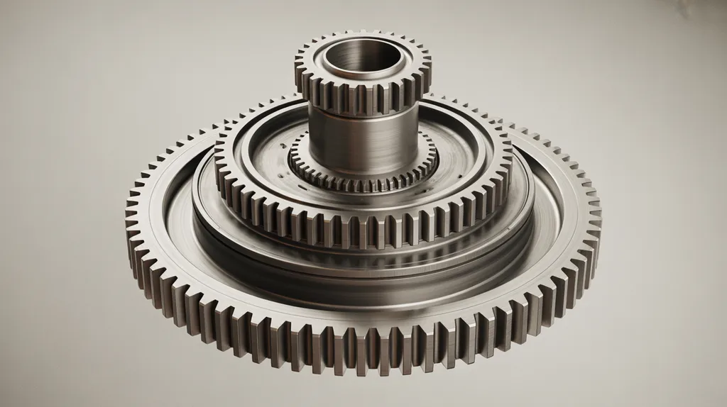
A planetary gearbox ratio is the relationship between input speed and output speed, set by which of the three members — sun gear, planet carrier or ring gear — is held fixed, and by their tooth counts. A planetary gear set is a compact arrangement where several planet gears rotate between a central sun gear and an outer ring gear while a carrier holds them in orbit.
Which member you lock determines the ratio range. According to tec-science, fixing the ring gear with the sun as input and the carrier as output gives a ratio of 1 + zring/zsun, which produces values above 2 and has no upper limit. Fixing the sun gear instead gives 1 + zsun/zring, a range between 1 and 2. Fixing the carrier gives −zring/zsun, where the negative sign signals that the output rotates in the opposite direction from the input.
[DIAGRAM: Labelled planetary gear set showing the sun gear, planet gears, ring gear and planet carrier, with input and output arrows.]
KHK illustrates the same set with mixed operating modes: for gear teeth za = 16, zb = 16 and zc = 48, the planetary arrangement gives a ratio of 4, the solar arrangement gives 1.33333, and the star arrangement gives −3. A 2013 engineering forum discussion on the same topic notes that all six combinations of fixed sun, fixed carrier and fixed ring are possible, and that some configurations reverse the output direction.
| Fixed member | Input | Output | Ratio form | Ratio range | What it means in practice |
|---|---|---|---|---|---|
| Ring gear | Sun gear | Planet carrier | i = 1 + zring/zsun | 2 < i < ∞ | The usual reduction mode; highest single-stage ratios |
| Sun gear | Ring gear | Planet carrier | i = 1 + zsun/zring | 1 < i < 2 | Very low ratios only |
| Planet carrier | Sun gear | Ring gear | i = −zring/zsun | −∞ < i < −1 | Negative sign means reversed rotation |
How Do You Calculate the Ratio From Motor Speed and Output Speed?
Divide the motor’s rated speed by the output speed the machine needs. The result is the ideal ratio, which you then match to the nearest ratio the gearbox manufacturer actually offers. This calculation is the practical starting point; tooth-count formulas come later if you need to verify a design.
Follow these steps:
- Record the motor’s rated speed in rpm, taken from the nameplate rather than from the nominal mains frequency.
- Record the output speed the machine requires, in rpm, from the driven shaft or the process requirement.
- Divide motor speed by required output speed to get the ideal ratio.
- Compare the result with practical single-stage limits.
- Select the nearest standard ratio rather than the mathematically exact one.
- Recalculate the actual output speed from the chosen ratio, and confirm it still falls inside the machine’s tolerance.
- Verify torque, efficiency, backlash and cost before ordering.
The recheck in step 6 is what most selection guides skip. A 30:1 requirement and a 28:1 catalogue ratio are close, but they are not the same machine behaviour, and the difference matters on a conveyor or a metering screw running at a fixed rate.
If you are comparing planetary units against other reducer families, the same speed division applies, and the wider method is set out in this guide to gearbox ratio selection.
How Do You Calculate Planetary Gear Ratio From Tooth Counts?
With the ring gear fixed, the ratio is one plus the ring tooth count divided by the sun tooth count. TEA gives the formula as i = 1 + zring/zsun and works through an example where a 24-tooth sun and a 72-tooth ring produce a ratio of exactly 4.0, with a 24-tooth planet gear.
Two constraints sit behind that arithmetic. Woodgears states the tooth-count relationship as R = 2P + S, where R is the ring, P is the planet and S is the sun, and notes that with the ring fixed the carrier turns by Ty = Ts·S/(R+S). KHK gives the assembly condition as zc = za + 2zb, and adds that at least two planet gears are normally used so the load is shared and balanced.
The Willis equation, nr·zr = nc·(zr + zs) − zs·n_s, describes the general motion of the three members when none is fixed, as set out by tec-science. It is useful background, but it is not needed for the speed-division method most selection work starts from.
Worked Example: 1,500 rpm Motor, 50 rpm Output
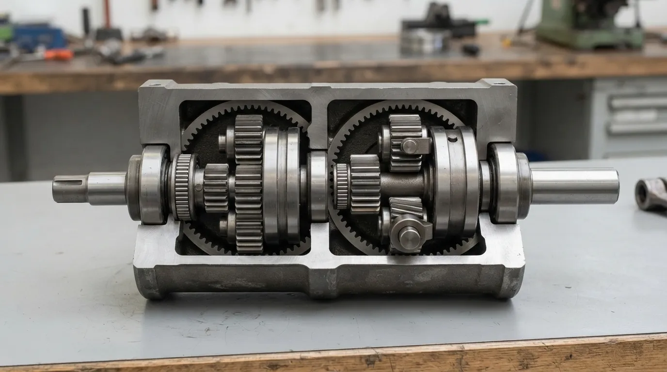
A 1,500 rpm motor and a 50 rpm output requirement give an ideal ratio of 30:1. According to Machine Design, single-stage planetary gearheads are practical from about 3:1 to 10:1, and ratios above 10:1 need an additional planetary stage. That places this application in two-stage territory rather than single-stage.
TEA gives the wider bands: single-stage units commonly cover 3:1 to 10:1, two-stage units cover roughly 9:1 to 100:1, and three-stage units can reach up to 1000:1. So a 30:1 duty sits comfortably inside a two-stage selection.
[DIAGRAM: Decision flow from a 1,500 rpm motor and a 50 rpm requirement, through a 30:1 ideal ratio, to the nearest standard ratio and a two-stage selection.]
| Ideal ratio | Likely stages | Output speed at 1,500 rpm input | Typical duty | Main trade-off |
|---|---|---|---|---|
| 3:1 to 10:1 | One | 150 to 500 rpm | General conveying, mixing, light indexing | None significant |
| 10:1 to 100:1 | Two | 15 to 150 rpm | Slower feeders, mixers, positioning | Extra stage adds length, cost and backlash |
| Above 100:1 | Three | Below 15 rpm | Very slow, high-torque duties | Longest unit, lowest efficiency, highest cost |
Single-Stage, Two-Stage or Three-Stage: Which Ratio Do You Need?
Use one stage for low ratios, add a second when the ideal ratio passes about 10:1, and add a third only when the required ratio is very high. Stage count is the decision that drives size, cost and accuracy, so it should be settled before the exact ratio is fixed.
Machine Design notes that ratios greater than 10:1 require an additional planetary stage, while ratios below 3:1 are impractical because the pinion and ring gear would end up nearly the same size. The same source reports that ratios between 4:1 and 8:1 give the best combination of pinion and planet-gear size, performance and life within a single stage.
| Stages | Typical ratio range (TEA) | Efficiency | Relative length and cost | Best-fit duty |
|---|---|---|---|---|
| One | 3:1 to 10:1 | About 97% per stage | Shortest and lowest cost | Standard conveying, mixing, general drive duty |
| Two | 9:1 to 100:1 | Drops with each added stage | Longer, higher cost | Slow outputs and higher torque requirements |
| Three | Up to 1000:1 | Lowest of the three | Longest, highest cost | Very slow, high-ratio duties |
Gear type also moves the numbers. Machine Design reports that helical planetary gearing has a contact ratio of 3.3 against a typical 1.5 for spur gearing, delivers 30–50% more torque capacity, and gains a further 17–20% in torque capacity when the helix angle is increased from 12° to 15°. Those are design-level options, not ratio changes, but they affect which stage count is viable for a given duty.
When the stage decision is still open, this comparison of single stage vs multi stage gearbox covers how length, efficiency and cost shift as stages are added. Stage count also feeds directly into material and machining content, which is one reason industrial gearbox price moves with the ratio band rather than with the housing size alone.
How Ratio Affects Output Torque, Speed and Efficiency
Ratio sets output speed directly, but output torque is not simply the input torque multiplied by the ratio. A high ratio does not guarantee usable torque, because the gearbox rating, the service factor and the efficiency losses all cap what reaches the driven shaft.
According to TEA, planetary gearbox efficiency typically sits between 95% and 98%, with each stage costing roughly 3%. That means a three-stage unit returns noticeably less of the motor’s power than a single-stage unit, and the loss appears as heat rather than as useful output torque. The same source recommends verifying load capacity against ISO 6336 or DIN 3990 rather than relying on the ratio alone.
| What changes as ratio rises | Effect | Why it matters |
|---|---|---|
| Output speed | Falls in proportion to the ratio | The driven shaft may run slower than the process needs |
| Available output torque | Rises in theory, but is limited by the gearbox rating | Peak and starting torque must be checked against the unit rating |
| Efficiency | Each added stage costs roughly 3% (TEA) | Lost power becomes heat, not torque |
| Backlash | Accumulates with each added stage | Positioning accuracy is affected, not just speed |
The practical rule is to size the gearbox on the required output torque and the duty cycle, then confirm the ratio produces an acceptable output speed. Running the calculation the other way round — choosing the ratio first and hoping the torque is enough — is how under-sized units reach the plant floor.
Backlash and Positioning: A Ratio Side Effect
Higher ratios usually mean more stages, and every added stage adds backlash, so positioning accuracy must be checked alongside the ratio. Backlash is the small amount of free rotation at the output before the gears engage in the opposite direction.
TEA gives reference points for positioning duties: below 1 arcmin for precision positioning, 2 to 5 arcmin for standard positioning, and up to 10 arcmin for conveyor technology. Machine Design cautions that backlash is not measured against one strict standard, and notes that a unit rated at 8 arcmin out of the box might reach 15 arcmin after six months of use. That ageing effect is a selection criterion, not a warranty detail.
If repeated positioning is part of the duty, the ratio decision and the accuracy decision should be made together; the tolerance side of that pairing is covered in this explanation of planetary gearbox backlash.
Common Planetary Gear Ratio Selection Mistakes
The most common failures are rounding the ratio without re-checking the resulting output speed, ignoring peak torque, and specifying a ratio that is not a standard offering. None of these are exotic errors; they happen when the calculation is treated as paperwork rather than as the design decision.
- Treating gear ratio and reduction ratio as interchangeable without checking which convention the supplier uses.
- Choosing the mathematically ideal ratio instead of the nearest standard ratio, then discovering the output speed is wrong.
- Sizing on running torque only, and ignoring starting torque or shock loads.
- Assuming backlash is a fixed catalogue number that will not change over the life of the unit.
- Assuming a planetary gearbox will hold a load the way a self-locking worm gearbox can; back-drivability should be confirmed with the supplier for the specific duty.
- Forgetting that each extra stage adds length, cost and efficiency loss, which can outweigh the benefit of a finer ratio match.
- Requesting a quote for a ratio before confirming it is available as standard.
Matching the Ratio to Your Machine — and to Your Supplier

Once the ratio and stage count are fixed, the remaining variables are mounting dimensions and availability. These are the points where an OEM build usually differs from a catalogue selection.
If the drive duty is still being defined — load profile, starts per hour, ambient conditions — work through how to choose planetary gearbox before locking the ratio. Duty cycle also varies by industry; typical duty patterns for mixers, conveyors and process lines are described in these planetary gearbox applications.
Mingye designs, makes and supplies industrial power transmission equipment from Jinshan District, Shanghai, including heavy-duty planetary reducers within a range of more than 20 series. Both motors and reducers are built in the company’s own CNC-equipped factory on modular, standardized designs, and OEM customization of mounting dimensions and transmission ratios is available, with normal delivery of 7–15 days. OEMs and plant engineers can send motor speed, required output speed and mounting constraints for a ratio review.
FAQ
What is the difference between gear ratio and reduction ratio?
A reduction ratio usually describes input speed relative to output speed in a speed-reducing drive, while gear ratio describes the relationship between the two shafts more generally. Many suppliers use the two terms interchangeably, so confirm which convention appears on the data sheet before you place an order based on the figure.
Does a higher planetary gear ratio cost more?
Usually yes, because higher ratios generally require additional stages, which add gears, bearings, housing length and machining. A single-stage unit in the 3:1 to 10:1 range contains fewer parts than a two-stage unit covering 9:1 to 100:1, so compare the nearest standard ratio before assuming a custom ratio is the cheaper route.
What happens if I choose a ratio that is not standard?
The actual output speed will differ from the required figure and may fall outside the machine’s tolerance. Always recalculate the output speed from the standard ratio you select, and confirm the deviation is acceptable for the process before committing to the design. This check takes a minute and prevents a rework cycle.
How much efficiency is lost per planetary stage?
According to TEA, each planetary stage costs roughly 3%, giving 95% to 98% overall efficiency for a typical multi-stage planetary gearbox. The loss appears as heat, and it reduces the torque actually available at the output, so efficiency belongs in the torque calculation rather than in a footnote.
Share on Social:


Contact Us
Rubber Internal Mixer Gearbox: Read the Batch Load Profile, Not Just Motor kW
Oct 22, 2026
Hot Industrial Gearbox Coupling After Cold Alignment: What to Check
Oct 22, 2026
Hydraulic Slewing Drive Won't Rotate: Separate Motor, Brake and Gearbox Faults
Oct 22, 2026
Calender Roll Gap Changes: What Must the Drive Coupling Accommodate?
Oct 22, 2026