


 Home /
How to Design a Custom Gearbox for Industrial Equipment?

Right Angle Geared Motor: Matching Electrical Supply, Variable Speed and Braking
Oct 26, 2026

Planning a Bevel Reducer Installation: Turn Shaft Requirements Into a Practical Drive Layout
Oct 26, 2026

Choosing an Overhead Crane Gearbox by Its Hoisting or Travel Function
Oct 26, 2026

Replacing an Industrial Worm Gearbox: What to Keep and What to Reassess
Oct 25, 2026
To design a custom gearbox, start from the load specification — not from the gearbox. Define required output torque, input and output speeds, duty cycle, shock load, mounting orientation, and environmental conditions. Then determine the gear ratio and number of stages, select the gear type, design housing, bearings, and shafts, and validate the design before manufacturing.
What Is a Custom Gearbox and When Do You Need One?
A custom gearbox is a speed-reduction unit engineered to meet application specifications that standard catalog gearboxes cannot satisfy. Unlike off-the-shelf units, a custom gearbox is designed around non-standard ratios, unusual mounting arrangements, or special environmental conditions.
According to Superior Gearbox Company, a custom gearbox provides solutions that standard gearboxes cannot, with customization possible across mounting options, gear ratios, housing materials, and shaft orientation. Standard gearboxes are designed to cover the most common industrial needs; a custom gearbox becomes necessary when your application requires something outside those common parameters.
Consider a custom design when you need a ratio that falls between standard offerings, a specific mounting configuration that does not match any catalog unit, or a housing material suited for a corrosive or wash-down environment. Before committing to a fully bespoke design, however, compare the engineering cost against the standard vs custom gearbox trade-offs — many "custom" requirements can be met with standard components modified at the interfaces.
Step 1 — Define the Load Specification
The first step in custom gearbox design is defining the load specification — the complete set of application data that determines every downstream engineering decision. According to Sumitomo Drive Technologies, a customized gearbox design starts with application data like required torque, input speed, output speed, duty cycle, shock load, and mounting configuration.
Load Specification Checklist
| Design Input | What to Determine | Typical Units |
|---|---|---|
| Output torque | Maximum torque the gearbox must deliver | N·m or lb-ft |
| Input speed | Speed of the motor or prime mover | rpm |
| Output speed | Required speed at the driven equipment | rpm |
| Gear ratio | Input speed ÷ output speed | Ratio (e.g., 20:1) |
| Duty cycle | Operating hours per day, starts/stops per hour | hours/day |
| Service factor | Accounting for shock load and load class | — |
| Mounting orientation | Foot, flange, shaft, or vertical mount | — |
| Space constraints | Center distance, envelope dimensions | mm or inches |
| Ambient temperature | Operating environment range | °C or °F |
| Environment | Dust, moisture, corrosive exposure | — |
According to Superior Gearbox Company, key design considerations include load capacity covering both static and dynamic loads, shock and overload conditions, speed requirements, and environmental conditions. The service factor is particularly important — it adjusts the design torque upward to account for shock loads, such as crushers, mixers with viscous materials, or conveyors with start-stop operation.
Do not skip the environmental assessment. A gearbox for a heated indoor cement plant faces different thermal and contamination conditions than one on a port conveyor exposed to salt spray. Ambient temperature affects lubricant selection, seal material, and housing cooling requirements.
Step 2 — Determine the Gear Ratio and Number of Stages
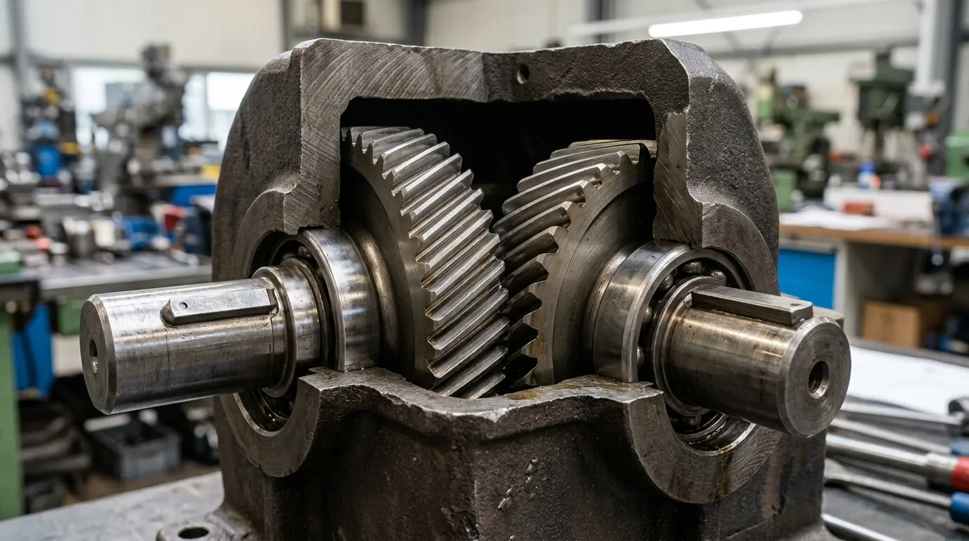
The gear ratio is the input speed divided by the output speed. A custom gearbox converts high-speed, low-torque power from a motor into low-speed, high-torque output — the ratio determines how much speed reduction and torque multiplication occurs.
According to Chamol Gear, the key parameters to calculate before designing a gearbox include power, rotational speed, torque, gear ratio, gear strength, and shaft design. The ratio calculation itself is straightforward; the design decision is how to achieve it.
Numbered Steps for Ratio and Stage Determination
- Calculate the required ratio: Ratio = input speed ÷ output speed. For example, a 1,450 rpm motor driving equipment at 58 rpm needs a 25:1 ratio.
- Compare against single-stage limits: A single helical gear pair handles approximately 1.5:1 to 7:1; a single planetary stage handles 3:1 to 10:1; a worm gear can achieve 5:1 to 60:1 in one stage.
- Plan multiple stages for higher ratios: For a 25:1 ratio with helical gears, use two stages (e.g., 5:1 × 5:1) rather than a single high-ratio pair. Multi-stage designs distribute load evenly across gear sets.
- Check thermal limits: High-ratio worm gears generate significant heat. For continuous-duty applications above approximately 10:1 with worm gearing, verify that the housing can dissipate the heat or plan for cooling.
The gearbox customization torque ratio mounting options you specify at this stage directly affect the number of stages needed. A higher ratio demands either more stages or a different gear type — this is where the economics of the design decision become clear.
Step 3 — Select the Gear Type
Gear type selection depends on three factors: shaft orientation (inline, parallel, or right angle), required ratio per stage, and efficiency priority. Each gear type serves a different combination of these constraints.
| Gear Type | Shaft Orientation | Ratio per Stage | Efficiency Range | Torque Density | Typical Applications |
|---|---|---|---|---|---|
| Helical (parallel shaft) | Inline / parallel | 1.5:1 – 7:1 | 96–98% | Medium | Conveyors, mixers, general industrial drives |
| Planetary | Inline (coaxial) | 3:1 – 10:1 | 95–97% | High | Compact high-torque: mining, rotating equipment |
| Bevel | Right angle | 1:1 – 5:1 | 93–97% | Medium | Right-angle drives, material handling |
| Worm | Right angle | 5:1 – 60:1+ | 50–90% | Low–medium | High-ratio compact, low-speed intermittent duty |
Helical gearboxes offer the best efficiency for inline and parallel shaft configurations. With 96–98% efficiency per stage, they suit continuous-duty applications like conveyors and mixers where energy cost matters. Their parallel-shaft design handles moderate torque density and is the most common industrial configuration.
Planetary gearboxes provide the highest torque density per stage because multiple planet gears share the load around a central sun gear. They are the best choice when you need high torque in a compact coaxial arrangement — common in mining equipment, rotary tables, and heavy industrial machinery where space is limited.
Bevel gearboxes change the direction of power transmission by 90 degrees. They suit right-angle drives in material handling, packaging lines, and any application where the motor must sit perpendicular to the driven shaft.
Worm gearboxes achieve high reduction ratios in a single, compact right-angle stage — up to 60:1 or higher. The trade-off is efficiency: worm drives range from approximately 50% to 90%, depending on ratio. They should not be selected for continuous high-speed operation, where heat generation becomes a design constraint.
The Design Basics of Industrial Gear Boxes technical reference notes that contact ratio should be a minimum of 1.2 for gear design — below this, the gear mesh becomes noisy and wears prematurely. This metric is typically verified during manufacturing inspection.
Step 4 — Design the Housing, Bearings, Shafts, and Seals
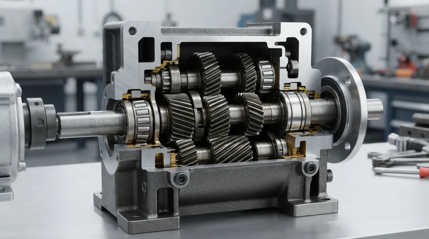
The housing, bearings, shafts, and seals must be designed for the actual loading conditions — not just for the gears themselves.
According to Superior Gearbox Company, design considerations must include both static and dynamic loads as well as shock and overload conditions. Bearings are sized for combined radial and axial loads using the L10 rating life method, which predicts the life that 90% of an identical bearing group will achieve. Shafts must be dimensioned for both torque and bending moment, with keyways and splines designed to transmit the full torque without stress concentrations.
Housing material selection follows the same logic as gear material choice:
- Cast iron: Provides excellent vibration damping and machinability — a good default for most industrial applications.
- Aluminum: Reduces weight and resists corrosion — preferred for wash-down environments and applications where weight is a constraint.
- Steel plate: Offers high strength for heavy shock loads and severe duty applications.
Seal selection depends on the environment. Lip seals handle standard dust and moisture exposure. For corrosive or wash-down environments, specify seals rated for chemical resistance. For high ambient temperatures, verify that seal material tolerates sustained operating conditions.
The housing must also manage heat. According to Superior Gearbox Company, simulation tools are used for virtual testing of thermal management — this is not an afterthought. A gearbox that runs continuously at high load needs sufficient housing surface area for heat dissipation or auxiliary cooling.
Step 5 — Validate the Design Before Manufacturing
Before manufacturing, validate the design with 3D modeling, virtual simulation, and — where risk is high — physical prototyping.
According to Superior Gearbox Company, CAD software is used to create detailed 3D models, followed by simulation tools that virtually test structural integrity, gear meshing, transmission efficiency, and thermal management. This validation step catches design errors before metal is cut, saving both time and cost.
Numbered Validation Process
- Build a 3D CAD model of the complete gearbox assembly with all components modeled in context.
- Run finite element analysis (FEA) on the housing, shafts, and bearing housings to verify structural integrity under maximum load and shock conditions.
- Simulate gear meshing and transmission to check tooth contact patterns, backlash, and load distribution across stages.
- Check thermal limits — verify that the housing dissipates heat adequately for continuous operation at full load.
- Prototype where risk is high — new gear geometry, unusual materials, or untested mounting configurations justify a physical prototype.
- Inspect and quality-control the finished gearbox. Manufacturing involves CNC machining, heat treatment, surface finishing, assembly, and rigorous quality control.
According to Aerospace Manufacturing and Design, a comprehensive gear design process includes evaluating design criteria and geometric constraints, calculating speeds, torque, and loads, and determining gear geometry — a 12-step engineering sequence. The six-step process above captures the essential workflow for most industrial custom gearbox projects.
Common Gearbox Design Mistakes to Avoid
The most common gearbox design mistakes result from undersizing for shock loads, ignoring duty cycle, and selecting the wrong gear type for thermal conditions.
- Undersizing for shock loads instead of steady loads: A crusher or mixer can impose impact loads several times the steady-state rating. Design the service factor for the worst case, not the average.
- Ignoring duty cycle: A gearbox that runs 8 hours per day with frequent starts faces different thermal and wear conditions than one that runs continuously. Design for the actual operating profile.
- Choosing worm drives for high-speed continuous duty: Worm gear efficiency drops significantly at high ratios — the resulting heat can exceed the housing's dissipation capacity. Select helical or planetary designs for continuous high-ratio applications.
- Skipping thermal validation: Enclosed gearboxes generate heat; if the housing cannot dissipate it, lubricant degrades and gear life shortens. Always verify thermal performance for continuous operation.
- Forgetting lubrication and cooling requirements: Oil level, oil type, and cooling method must be specified at the design stage, not left to field improvisation.
- Designing without checking service factors: AGMA and ISO service factors exist to account for load class, duty cycle, and prime mover characteristics. Using them is not optional for reliable industrial gearbox design.
When designing gear pairs, a practical tip from experienced gearbox designers: sketch the pitch diameter of all gears in the train and verify that mating gear pitch diameters are tangent. This simple check catches ratio and center-distance errors before detailed design begins.
How Modular Standard Parts Shorten Custom Gearbox Design
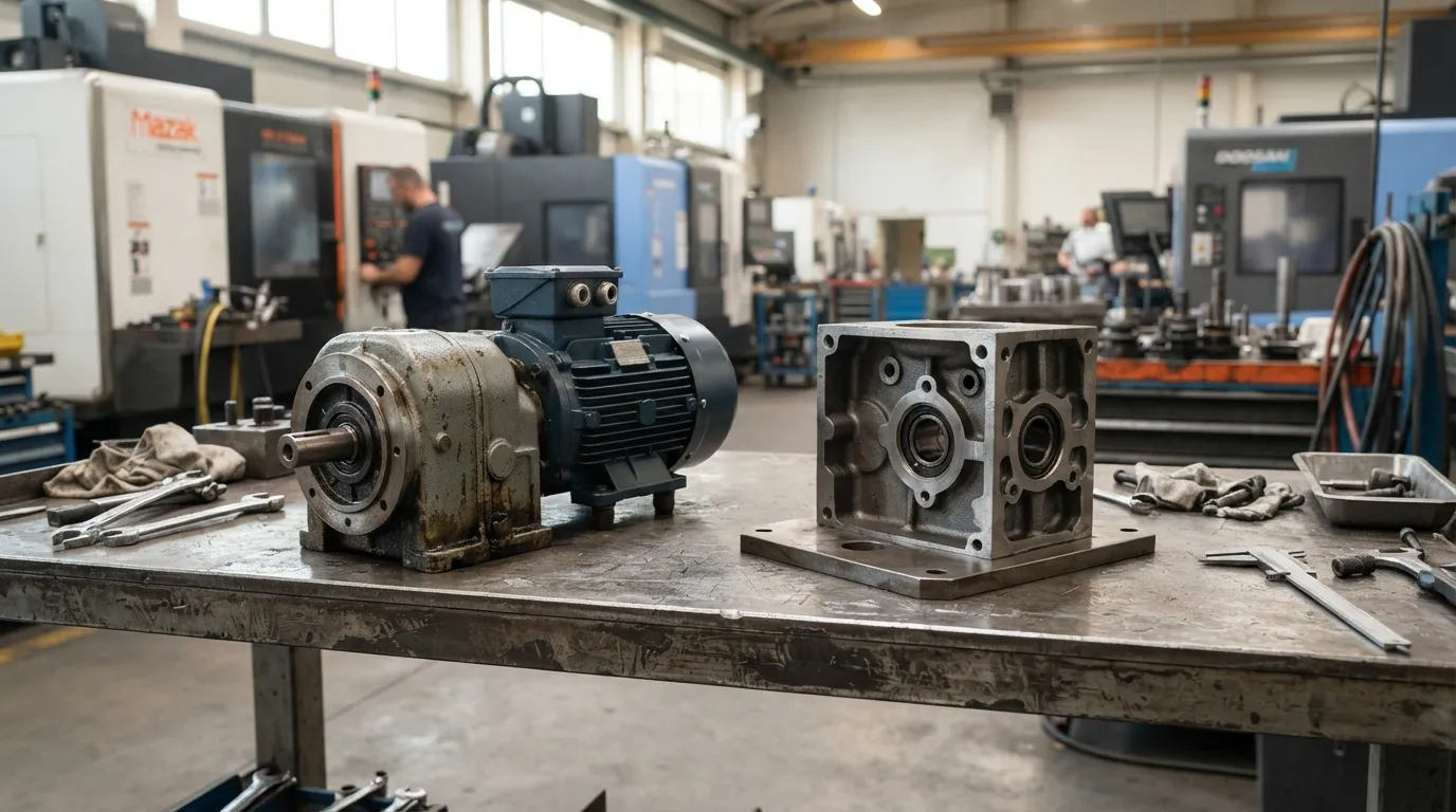
Custom gearbox design does not always mean starting from a blank page. Many "custom" gearboxes are built by combining modular standard components — proven motor and reducer series with customized ratios and mounting interfaces.
Mingye (Shanghai Mingye Machinery Co., Ltd.) builds both motors and reducers in its own CNC-equipped factory on modular, standardized designs. OEM customization of mounting dimensions and transmission ratios is offered as part of the engineering process, and normal delivery is within 7–15 days.
| Fully Bespoke Design | Modular Standard Parts + Customization |
|---|---|
| New gear geometry for every project | Proven gear geometry reused across projects |
| Full FEA and prototyping cycle required | Validation limited to interface changes |
| Longer lead time — weeks to months | Shorter lead time — typically 7–15 days |
| Higher engineering cost | Lower engineering cost, focused on integration |
The practical implication: before specifying a fully besigned gearbox, ask whether the required ratio and mounting can be achieved with standard gear sets and custom flanges, input shafts, or output shafts. For most industrial applications — conveyors, mixers, packaging lines — modular customization covers the requirement at a fraction of the engineering cost and lead time.
For custom gearbox quote information on Mingye's modular customization options, the engineering team works from your load specification to determine which standard series (R, S, K, F helical; HB heavy-duty; planetary; NMRV worm) can be adapted to your mounting and ratio requirements.
Summary — A Step-by-Step Custom Gearbox Design Checklist
Follow this checklist to design a custom gearbox for your industrial equipment:
- Define the load specification — torque, speed, duty cycle, shock load, mounting, environment.
- Calculate the gear ratio and number of stages — ratio equals input speed ÷ output speed; add stages when the ratio exceeds single-stage limits.
- Select the gear type — helical for inline efficiency, planetary for torque density, bevel for right-angle, worm for compact high-ratio.
- Design the housing, bearings, shafts, and seals — sized for actual loads, shock conditions, and environmental exposure.
- Validate with CAD, FEA, and simulation — catch errors before manufacturing, prototype where risk is high.
- Consider modular standard parts first — custom mounting and ratios on proven gear sets shorten lead time and reduce engineering cost.
Mingye's factory in Jinshan District, Shanghai, designs and manufactures more than 20 series of gearboxes and gear motors, covering helical, planetary, worm, cycloidal, and cylindrical configurations. The about us page details the company's manufacturing capabilities and the industries it serves — plastics and rubber, mixing, conveying and material handling, packaging, mining, cement, power, and ports.
If you are evaluating the investment side of a custom gearbox project, the industrial gearbox price guide explains how design complexity, materials, and modular versus bespoke approaches affect cost.
Share on Social:


Contact Us
In This Article
Right Angle Geared Motor: Matching Electrical Supply, Variable Speed and Braking
Oct 26, 2026
Planning a Bevel Reducer Installation: Turn Shaft Requirements Into a Practical Drive Layout
Oct 26, 2026
Choosing an Overhead Crane Gearbox by Its Hoisting or Travel Function
Oct 26, 2026
Replacing an Industrial Worm Gearbox: What to Keep and What to Reassess
Oct 25, 2026