


 Home /
Mining Gearbox Predictive Maintenance: Vibration and Oil Analysis Guide

Right Angle Geared Motor: Matching Electrical Supply, Variable Speed and Braking
Oct 26, 2026

Planning a Bevel Reducer Installation: Turn Shaft Requirements Into a Practical Drive Layout
Oct 26, 2026

Choosing an Overhead Crane Gearbox by Its Hoisting or Travel Function
Oct 26, 2026

Replacing an Industrial Worm Gearbox: What to Keep and What to Reassess
Oct 25, 2026
A Mining Gearbox operating a crusher, conveyor, feeder, or mill is exposed to conditions very different from a general-purpose industrial reducer. Repeated shock loads, variable torque, abrasive dust, long duty cycles, contamination, and limited maintenance windows can accelerate gear and bearing damage.
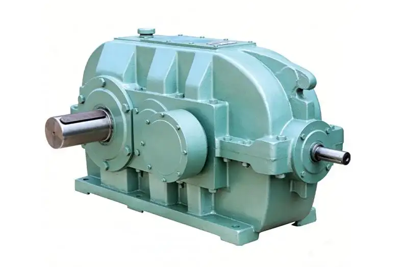
From Mingye's engineering perspective, reliable Mining Gearbox operation starts with two things: correct transmission selection and condition data that can distinguish normal process variation from progressive mechanical deterioration.
The objective of condition monitoring is not simply to collect vibration or oil data. It is to answer a practical maintenance question:
Can the Mining Gearbox continue operating, should it be monitored more closely, or does it require planned inspection or shutdown?
Why Mining Gearbox Failures Rarely Depend on One Parameter
Typical Mining Gearbox deterioration mechanisms include:
• Gear tooth pitting, micropitting, scuffing, or localized damage
• Rolling-element bearing fatigue
• Shaft or coupling misalignment
• Excessive backlash or looseness
• Lubricant viscosity loss or oxidation
• Water and abrasive particle contamination
• Repeated peak torque and impact loading
• Seal degradation and oil leakage
These mechanisms develop differently. A bearing defect may create high-frequency impacts before overall vibration becomes severe. Gear surface wear may first appear through wear debris or changing gear-mesh sidebands. Overloading may raise temperature without immediately producing a permanent mechanical defect.
For this reason, a professional Mining Gearbox condition-monitoring strategy should combine:
Vibration + Lubricant Condition + Temperature + Load Context + Trend History
Reading Mining Gearbox Vibration Beyond Overall RMS
Overall vibration velocity in mm/s RMS is useful for screening, but it cannot identify every gearbox fault.
Frequency-domain analysis is more valuable when determining whether a vibration increase comes from shaft rotation, gear meshing, bearings, structural looseness, or operating load.
Gear Mesh Frequency
Gear Mesh Frequency is related to gear tooth count and rotational speed:
GMF = Number of Gear Teeth × Shaft Rotational Frequency
An increase at GMF does not automatically mean tooth failure because gear-mesh amplitude also changes with transmitted load.
More useful diagnostic information often comes from:
• GMF amplitude trend
• Harmonics of GMF
• Sidebands around GMF
• High-frequency acceleration
• Envelope spectrum
• Changes relative to a stable operating baseline
| Signal Feature | Possible Engineering Interpretation |
| Rising 1× rotational frequency | Imbalance, alignment, shaft-related effects |
| Increasing GMF | Load change or changing gear-mesh condition |
| GMF with strong sidebands | Modulation, eccentricity, localized wear, load variation |
| Repetitive impacts | Possible localized tooth or bearing damage |
| Envelope-frequency peaks | Possible rolling-element bearing defects |
| Broadband vibration increase | Looseness, severe wear, structural or process influence |
The important word is possible. A Mining Gearbox should not be diagnosed from one spectral peak without considering speed, load, history, and sensor position.
Oil Analysis Shows What Vibration Cannot
Lubricant circulates through the internal contact surfaces of a Mining Gearbox and can reveal contamination, lubricant degradation, and wear before severe vibration develops.
Useful oil-analysis parameters include:
• Kinematic viscosity
• Water content
• Particle count
• Ferrous debris
• Iron and other wear elements
• Oxidation
• Acid number
• Oil temperature
Wear Metals Need Trending
A high iron concentration does not automatically mean a Mining Gearbox has damaged gear teeth. Iron may originate from gears, shafts, bearings, or other steel components.
Interpretation should consider:
• Previous sample trend
• Lubricant operating hours
• Recent oil changes or top-up
• Particle size
• Other wear elements
• Vibration changes
• Actual gearbox load
This is why repeated samples taken under consistent conditions are more useful than isolated laboratory reports.
How Temperature, Viscosity and Wear Interact
Temperature should not be treated as an independent alarm.
As lubricant temperature rises, viscosity generally falls. If viscosity becomes too low for the operating load, elastohydrodynamic film thickness can decrease, increasing the risk of surface interaction, wear, and eventually higher vibration.
The diagnostic relationship is therefore:
Temperature ↑ → Viscosity ↓ → Film Thickness ↓ → Wear Risk ↑
However, the opposite extreme also matters. Excessively high viscosity during cold startup can increase churning losses, reduce circulation efficiency, and raise startup torque.
A Mining Gearbox lubrication strategy must therefore match viscosity to load, speed, ambient conditions, and gearbox design.
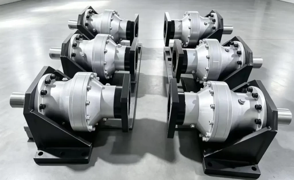
Vibration Analysis vs. Oil Analysis
These methods should complement each other rather than compete.
| Condition-Monitoring Method | Strongest Use | Main Limitation |
| Overall vibration | Fast condition screening | Limited fault localization |
| FFT spectrum | Gear mesh and rotational analysis | Sensitive to operating condition |
| Envelope analysis | Early rolling-bearing impacts | Requires suitable data quality |
| Laboratory oil analysis | Wear, contamination, lubricant condition | Sampling interval and delay |
| Online temperature | Rapid thermal trend | Low diagnostic specificity |
| Online vibration | Continuous mechanical trend | Higher system cost |
For a critical Mining Gearbox, confidence increases when several indicators move together.
For example:
GMF Sidebands ↑ + Ferrous Debris ↑ + Temperature ↑
Requires more attention than:
Vibration ↑ only during a temporary crusher impact event.
Match Monitoring Strategy to Mining Duty
Not every Mining Gearbox requires continuous online monitoring.
Crusher Mining Gearbox
Crusher drives experience:
• High peak torque
• Repeated torsional shocks
• Variable feed conditions
• Short-duration impact events
Monitoring must distinguish process impact from persistent mechanical degradation.
Conveyor Mining Gearbox
Conveyor drives often operate for long periods under relatively predictable duty. Important monitoring areas include:
• Bearing condition
• Alignment
• Gear-mesh trend
• Lubricant contamination
• Startup torque events
This makes conveyors particularly suitable for long-term trending.
Mill and Heavy-Duty Drives
Large mill drives place high continuous torque on gears and bearings. Monitoring should emphasize:
• Gear-mesh condition
• Bearing vibration
• Thermal stability
• Lubricant cleanliness
• Long-term wear trends
Periodic or Continuous Monitoring
The correct decision depends on machine criticality.
Continuous monitoring is more appropriate when:
• Failure can stop a major production line
• The Mining Gearbox is difficult to access
• Failure consequences are expensive
• Load is high and operation is continuous
• Developing faults need rapid detection
Periodic monitoring may be sufficient when:
• The gearbox has standby redundancy
• Inspection access is easy
• Production consequences are limited
• Failure development is relatively slow
Predictive maintenance should therefore be criticality-based, not sensor-based.
Sensor Position and Sampling Quality Affect Diagnosis
Poor measurement practice can hide or exaggerate Mining Gearbox faults.
Vibration sensors should normally be positioned close to bearing load paths. Depending on gearbox geometry, horizontal, vertical, and axial measurements may all be useful.
For trend reliability, maintain consistent:
• Sensor locations
• Mounting methods
• Measurement direction
• Machine speed
• Operating load
• Sampling settings
Oil samples should also come from representative circulating oil rather than stagnant dead zones or heavily settled reservoir bottoms.
A useful maintenance rule is:
Baseline before alarm limit. Trend before single reading. Multiple indicators before shutdown.
Prioritizing Data for Maintenance Decision-making
A Gearbox Monitoring Program will help crystallize a decision pathways framework as follows:
Normal > Watch > Investigate > Plan Maintenance > Shutdown
Considering data combinations of even slightly rising GMF and increased iron debris with an increase in temperature, would justify a borescope inspection or planned maintenance.
In the case of short, sharp spikes in vibration data that are caused by an overload, the process data should be assessed first before a decision to intervene internally and excavate gearbox damage is made.
This reduces both catastrophic failure risk and unnecessary maintenance.
Standards Support the Monitoring Process
Mining Gearbox monitoring programs can reference established machinery-condition standards such as:
• ISO 20816-9 for vibration measurement and evaluation of gear units
• ISO 13373 for vibration condition monitoring and diagnostics
• ISO 17359 for establishing machine condition-monitoring programs
• Relevant lubricant analysis and industrial gear lubrication standards
Standards should support measurement consistency and decision-making. They should not be simplified into one universal vibration limit for every Mining Gearbox.
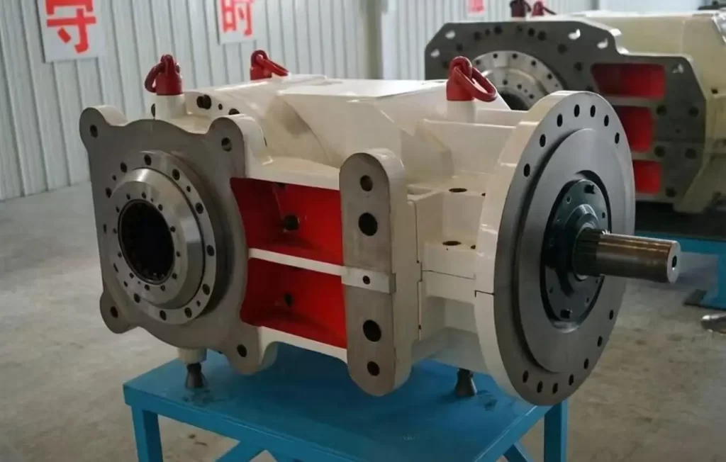
Mingye's Approach to Mining Gearbox Selection
Condition monitoring cannot compensate for an incorrectly selected transmission.
At Mingye, Mining Gearbox selection should begin with actual operating data:
• Motor power
• Input and output speed
• Reduction ratio
• Nominal torque
• Peak and shock torque
• Duty cycle
• Radial and axial loads
• Mounting arrangement
• Ambient temperature
• Dust and moisture exposure
• Lubrication and maintenance requirements
Mingye manufactures heavy-duty helical and bevel gearboxes, cylindrical gear reducers, and planetary gear reducers for demanding industrial transmission applications. Manufacturing capabilities such as precision gear machining, gear grinding, CNC processing, and dimensional inspection support stable gear geometry and repeatable assembly—important foundations for long-term Mining Gearbox reliability.
For crushers, conveyors, feeders, mills, and other mining machinery, the better approach is to treat the Mining Gearbox, driven machine, load profile, lubrication system, and monitoring strategy as one transmission system.
If you are selecting or upgrading a Mining Gearbox, visit Mingye to discuss torque, ratio, mounting, duty cycle, and operating conditions before finalizing the transmission configuration.
FAQs
Q1. What types of Mining Gearbox solutions does Mingye offer?
Mingye supplies industrial transmission solutions including heavy-duty helical and bevel gearboxes, cylindrical gear reducers, and planetary gear reducers suitable for demanding mining applications.
Q2. Can Mingye provide Mining Gearbox solutions for crushers and conveyors?
Yes. Mingye can evaluate gearbox configurations for crushers, conveyors, feeders, mills, and other heavy-duty mining machinery based on actual operating requirements.
Q3. What information does Mingye need to select a Mining Gearbox?
Key data normally includes motor power, input speed, required output speed, reduction ratio, nominal torque, peak torque, duty cycle, mounting arrangement, and operating environment.
Q4. Can Mingye customize a Mining Gearbox for specific mining equipment?
Mingye can evaluate customized transmission configurations when standard gearbox arrangements do not fully match the required ratio, torque, shaft arrangement, mounting position, or duty conditions.
Q5. How does Mingye consider shock loads when selecting a Mining Gearbox?
Mining applications may generate substantial transient torque. Mingye can consider peak torque, starting conditions, load variation, and shock-loading characteristics during gearbox selection.
Share on Social:


Contact Us
In This Article
Right Angle Geared Motor: Matching Electrical Supply, Variable Speed and Braking
Oct 26, 2026
Planning a Bevel Reducer Installation: Turn Shaft Requirements Into a Practical Drive Layout
Oct 26, 2026
Choosing an Overhead Crane Gearbox by Its Hoisting or Travel Function
Oct 26, 2026
Replacing an Industrial Worm Gearbox: What to Keep and What to Reassess
Oct 25, 2026