


 Home /
Planetary Gearbox vs Cycloidal Gearbox: What's the Difference?

Right Angle Geared Motor: Matching Electrical Supply, Variable Speed and Braking
Oct 26, 2026

Planning a Bevel Reducer Installation: Turn Shaft Requirements Into a Practical Drive Layout
Oct 26, 2026

Choosing an Overhead Crane Gearbox by Its Hoisting or Travel Function
Oct 26, 2026

Replacing an Industrial Worm Gearbox: What to Keep and What to Reassess
Oct 25, 2026
Planetary and cycloidal gearboxes differ fundamentally in how they transmit torque: planetary gearboxes use meshing gears arranged around a central sun gear, while cycloidal gearboxes use an eccentric cam that rolls a lobed disc against pins inside a ring gear. Cycloidal gearboxes offer lower backlash (0.1–0.2 arcmin vs 1–3 arcmin), higher shock-load tolerance, and higher single-stage reduction ratios, while planetary gearboxes deliver better efficiency across a wider speed range and are more cost-effective at ratios below 30:1.
- Cycloidal gearboxes achieve 0.1–0.2 arcmin pure backlash vs 1–3 arcmin for planetary gearboxes.
- Cycloidal gearboxes offer approximately 50% shorter and lighter form factor than multi-stage planetary gearboxes of comparable performance.
- Cycloidal gearboxes provide 500% higher overload safety compared to planetary gearboxes.
- Planetary gearboxes have the advantage at ratios below 30:1; cycloidal gearboxes excel at 30:1–300:1 in single-stage designs.
- Choose planetary for efficiency and speed; choose cycloidal for shock loads, high ratios, and precision positioning.
What Is a Planetary Gearbox?
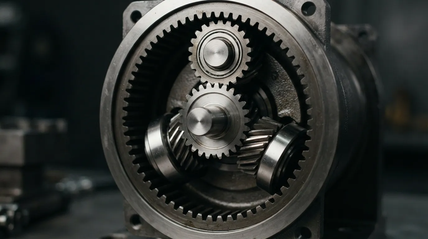
A planetary gearbox (also called an epicyclic gearbox) is a reduction drive that transmits torque through a central sun gear, planet gears mounted on a rotating carrier, and a fixed outer ring gear. All gears mesh simultaneously, which distributes the load across multiple contact points and gives planetary gearboxes their high power density.
The working principle follows a clear sequence:
- The input shaft drives the central sun gear.
- The sun gear rotates the planet gears, which are mounted on a planet carrier.
- The planet gears roll against the inner teeth of the fixed ring gear.
- The planet carrier rotates and delivers the output torque at a reduced speed.
Planetary gear systems achieve reduction ratios from 1:1 to virtually any value, but multiple stages are typically required for higher reductions. According to Omme, planetary reduction ratios typically range from 3:1 in a single-stage design to 100:1 and above in multi-stage configurations. Notably, planetary gearing achieves higher ratios than ordinary gear reductions by about 20% for the same tooth count, because the ring gear adds an extra engagement path.
What Is a Cycloidal Gearbox?
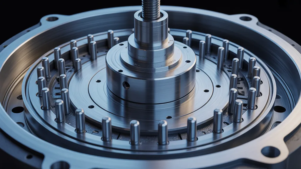
A cycloidal gearbox is a reduction drive that uses an eccentric cam on the input shaft to roll one or more lobed cycloidal discs against pins and rollers inside a ring gear. This mechanism converts eccentric motion into smooth, high-torque rotation with minimal backlash.
The working principle follows a distinct sequence:
- The input shaft rotates an eccentric cam.
- The cam causes a lobed cycloidal disc to roll around the inside of a ring gear fitted with pins or rollers.
- As the disc rolls, it pushes against output pins mounted on the output shaft assembly.
- Each full rotation of the input advances the output by a small fraction, producing high reduction in a single stage.
Cycloidal gearboxes achieve reduction ratios from 30:1 to over 300:1 without additional preliminary stages, according to Nabtesco. A single cycloidal stage can deliver up to 119:1 reduction, and coupled stages can reach 300:1, as noted by Omme. Because the cycloidal disc transmits motion through compressive rolling contact — not gear tooth bending — the load distributes across a large contact area. Omme reports an overlap factor of up to 70% of the main surfaces in contact simultaneously, which is why cycloidal gearboxes handle shock loads so well.
Planetary vs Cycloidal Gearbox: Side-by-Side Comparison
The table below summarizes the key differences across the attributes engineers compare when selecting between these two gearbox technologies.
| Feature | Cycloidal Gearbox | Planetary Gearbox |
|---|---|---|
| Working principle | Eccentric cam + lobed disc + ring pins | Sun gear + planet gears + ring gear |
| Single-stage reduction ratio | 30:1–119:1 (up to 300:1 with coupled stages) | 3:1–10:1 (100:1+ with multiple stages) |
| Backlash (pure) | 0.1–0.2 arcmin | 1–3 arcmin |
| Hysteresis loss | Significantly lower than planetary | More than 1 arcmin |
| Shock/overload tolerance | 500% higher overload safety | Standard overload capacity |
| Efficiency | Lower at low ratios; improves at high ratios | Higher and consistent across range |
| Size/weight | ~50% shorter and lighter than equivalent multistage planetary | Longer, cylindrical form factor |
| Maintenance | Lower (rolling contact, fewer wear points) | Moderate (gear wear over time) |
| Cost | Higher precision manufacturing costs | Lower mass-production costs |
| Typical applications | Robotics, precision positioning, shock loads | Automation, conveyors, general industrial |
Key Differences Explained in Detail
Working Principle: Gears vs Cam-and-Disc
Planetary gearboxes rely on gear tooth meshing under bending and shear stress. The teeth of the sun gear, planet gears, and ring gear must continuously engage and disengage, which creates localized stress concentrations at each contact point.
Cycloidal gearboxes transmit torque through compressive rolling contact. The cycloidal disc rolls against pins rather than meshing teeth, and because up to 70% of the main surfaces remain in contact simultaneously, the stress per unit area is much lower. This fundamental mechanical difference — bending and shear versus compression — explains why cycloidal gearboxes handle impacts and overloads better over an extended service life.
Reduction Ratio per Stage: Where Each Type Wins
The ratio capability per stage is one of the clearest differentiators between the two designs.
| Ratio Requirement | Better Choice |
|---|---|
| Below 10:1 | Planetary |
| 10:1–30:1 | Either (planetary often cheaper) |
| 30:1–119:1 | Cycloidal (single-stage) or planetary (multi-stage) |
| 119:1+ | Cycloidal (coupled stages) or planetary (multi-stage) |
Cycloidal gearboxes achieve high ratios in a single stage because each revolution of the eccentric cam advances the output by only a fraction of a rotation — the lobe count and pin count determine the ratio. Nabtesco notes that cycloidal gears offer ratios from 30:1 to over 300:1 without extra preliminary stages, while planetary gearboxes need multiple stacked stages to reach comparable ratios. According to Nabtesco, planetary gearboxes have the advantage when reduction ratios below 30:1 are required.
The practical consequence is that for a given high ratio, a cycloidal gearbox is approximately 50% shorter and lighter than a multi-stage planetary gearbox of comparable performance, as reported by Nabtesco. If installation space is tight or weight matters, this difference can be decisive. For low ratios, however, a planetary gearbox achieves the same result in a simpler and more compact way.
Shock Load Tolerance: Why Cycloidal Handles Impacts Better
Cycloidal gearboxes tolerate shock loads significantly better than planetary gearboxes. According to Nabtesco, cycloidal gears offer 500% higher overload safety compared to planetary gears.
The reason lies in the contact mechanics. When a shock load hits a planetary gearbox, the force concentrates on the few teeth that happen to be engaged at that moment. In a cycloidal gearbox, the compressive load spreads across a large percentage of the disc surface — up to 70% of the main surfaces in contact simultaneously, as reported by Omme. This means the impact force distributes over a much larger area, reducing peak stress.
Nabtesco also notes that cycloidal gears transmit the same nominal torque while offering higher acceleration torque (peak torque) and higher emergency stop torque than planetary gears. For applications with frequent starts, stops, reversals, or impact loading — such as presses, mixers, or indexing tables — this shock tolerance is often the deciding factor.
Backlash: Precision Positioning Differences
Backlash is the amount of lost motion between the input and output when the direction of rotation reverses. It directly affects positioning accuracy in servo-driven applications.
Cycloidal gearboxes offer pure backlash of 0.1–0.2 arcmin, while conventional planetary gearboxes typically have 1–3 arcmin, according to Nabtesco. This is an order-of-magnitude difference in precision. For example, in a robotic arm or a CNC positioning axis, that difference translates directly into how precisely the end effector or workpiece can be placed.
| Metric | Cycloidal | Planetary |
|---|---|---|
| Pure backlash | 0.1–0.2 arcmin | 1–3 arcmin |
| Hysteresis loss | Significantly lower | More than 1 arcmin |
| Backlash over service life | Very little increase | Tends to increase |
The advantage of cycloidal gearboxes extends beyond initial values. Nabtesco reports that in cycloidal gears, backlash increases extremely little over service life, while planetary gear backlash tends to increase as gear teeth wear. Hysteresis loss — the elastic deformation under load — is also more than 1 arcmin in precision planetary gearboxes but significantly lower in cycloidal designs. For machine builders who need consistent positioning accuracy over years of operation, cycloidal gearboxes offer a distinct advantage. For deeper detail on how planetary backlash compares across quality grades, see our dedicated article on planetary gearbox backlash.
Efficiency: Speed and Ratio Trade-offs
Planetary gearboxes are generally more efficient across a wider range of speeds and ratios. Their gear teeth roll and slide with predictable friction characteristics, and each stage adds only a small efficiency loss.
Cycloidal gearboxes are inefficient at low reduction ratios — below approximately 30:1 — which makes them less suitable for high-speed applications that do not need large reductions, according to Source Robotics. At higher ratios, however, cycloidal efficiency improves and becomes competitive, especially when compared to a multi-stage planetary gearbox that accumulates losses across several stages.
The practical guidance is straightforward: if you need high-speed operation with a modest ratio, choose a planetary gearbox. If you need a high ratio in a single stage and can accept the efficiency trade-off at low ratios, a cycloidal gearbox may serve better — particularly when space is constrained.
Cost Comparison: Precision vs Simplicity
Cycloidal gearboxes generally cost more per unit than planetary gearboxes, but the reasons are specific and worth understanding before you compare quotes.
The higher cost of cycloidal gearboxes comes from precision manufacturing of the eccentric cam, the lobed disc profile, and the hardened pins — components that must hold tight tolerances to deliver low backlash and long service life. The cycloidal disc shape is complex to machine, and the assembly requires careful matching of components.
Planetary gearboxes benefit from simpler mass-production methods. Their components — gears, carriers, and housings — are suitable for high-volume manufacturing with standard gear-cutting processes. Transcyko notes that a larger standard planetary gearbox may be more cost-effective than a high-performance compact cycloidal gearbox, especially when the application does not demand cycloidal-level precision or shock tolerance.
For budget-sensitive applications where backlash below 3 arcmin is not required and shock loads are moderate, a planetary gearbox is usually the more economical choice. For precision positioning, high shock loads, or compact high-ratio designs, the cycloidal premium is often justified by longer service life and better performance.
How to Choose: Decision Rule by Load Type
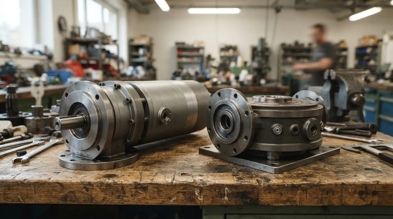
Choose a planetary gearbox when you need efficiency, high speeds, and ratios below 30:1. Choose a cycloidal gearbox when you have shock loads, need ratios above 30:1 in one stage, or require precision positioning with minimal backlash.
| Application Condition | Recommended Gearbox | Key Reason |
|---|---|---|
| Ratio below 30:1, high efficiency needed | Planetary | Better efficiency, lower cost |
| High shock loads, impact loading | Cycloidal | 500% higher overload safety |
| Precision positioning (backlash-critical) | Cycloidal | 0.1–0.2 arcmin pure backlash |
| High ratio in compact space | Cycloidal | 30:1–119:1 single-stage, 50% shorter |
| High-speed operation | Planetary | Better efficiency at speed |
| Cost-sensitive application | Planetary | Simpler production, wider availability |
| High torque in same dimensions | Planetary | Better torque capability per size |
The most important decision criterion is the nature of your load. If your application involves frequent shock loads, high peak torque, or emergency stops — and you need a ratio above 30:1 — a cycloidal gearbox is the stronger candidate because of its 500% higher overload safety, as reported by Nabtesco. If your application runs at steady speeds with predictable loads and requires maximum efficiency, a planetary gearbox is the better fit.
Precision positioning applications — robotics, rotary indexing tables, antenna positioning, machine tool axes — should favor cycloidal gearboxes for their 0.1–0.2 arcmin backlash and minimal backlash growth over service life. For general industrial automation, conveyors, and material handling where backlash tolerances are more relaxed, planetary gearboxes deliver excellent value and performance.
For a more detailed selection process, see our guides on how to choose a cycloidal reducer and how to choose a planetary gearbox.
Application Examples: Where Each Gearbox Excels
Understanding typical applications helps connect the technical specifications to real-world requirements.
Cycloidal gearboxes excel in:
- Robotics and articulated arms, where compact size, low backlash, and high shock tolerance are critical.
- Precision rotary tables and indexing drives that must hold position accurately over long periods.
- Mixing and agitation equipment, where shock loads from material surges are common.
- Welding positioners and rotators that need smooth, low-speed, high-torque output.
- Packaging machinery requiring precise registration and repeatable positioning.
For a fuller overview of where this technology fits, see our guide to cycloidal gearbox applications.
Planetary gearboxes excel in:
- Conveyor drives and material handling systems where efficiency and reliability matter more than minimal backlash.
- General industrial automation with moderate precision requirements and steady loads.
- Crane and hoist applications where high torque in a compact diameter is valuable.
- Servo motor applications in packaging, printing, and other machinery that need high speeds and responsive control.
- Agricultural and construction equipment exposed to demanding operating conditions.
For a fuller overview of where planetary technology fits, see our guide to planetary gearbox uses.
Mingye's Approach: One Manufacturer for Both Technologies
Mingye designs and manufactures both cycloidal pinwheel reducers and heavy-duty planetary reducers in its own CNC-equipped factory. This dual-technology capability means selection advice is not biased toward one design — the recommendation is based on the application, not on what happens to be in stock.
Mingye's modular, standardized design approach allows OEM customization of mounting dimensions and transmission ratios for either gearbox type. The manufacturing facility in Jinshan District, Shanghai, produces both motors and reducers under one roof, with a typical delivery of 7–15 days.
For plant engineers and OEMs working in plastics and rubber, mixing, conveying and material handling, packaging, mining, cement, power, and ports, Mingye can supply either technology matched to the specific load profile and ratio requirement. Because both gearbox types are built in-house, switching between them — or sourcing both from one supplier — does not require coordinating with multiple vendors.
Share on Social:


Contact Us
In This Article
Right Angle Geared Motor: Matching Electrical Supply, Variable Speed and Braking
Oct 26, 2026
Planning a Bevel Reducer Installation: Turn Shaft Requirements Into a Practical Drive Layout
Oct 26, 2026
Choosing an Overhead Crane Gearbox by Its Hoisting or Travel Function
Oct 26, 2026
Replacing an Industrial Worm Gearbox: What to Keep and What to Reassess
Oct 25, 2026