


 Home /
What Size Gear Motor Do I Need?

Right Angle Geared Motor: Matching Electrical Supply, Variable Speed and Braking
Oct 26, 2026

Planning a Bevel Reducer Installation: Turn Shaft Requirements Into a Practical Drive Layout
Oct 26, 2026

Choosing an Overhead Crane Gearbox by Its Hoisting or Travel Function
Oct 26, 2026

Replacing an Industrial Worm Gearbox: What to Keep and What to Reassess
Oct 25, 2026
To choose the right gear motor size, determine the load’s required output speed and torque first, including starting and shock loads. Then apply an appropriate service factor for duty cycle and operating conditions, calculate the reduction ratio and motor power, and confirm voltage, mounting, shaft loads and environment before selecting a model.
What Does “Gear Motor Size” Mean?
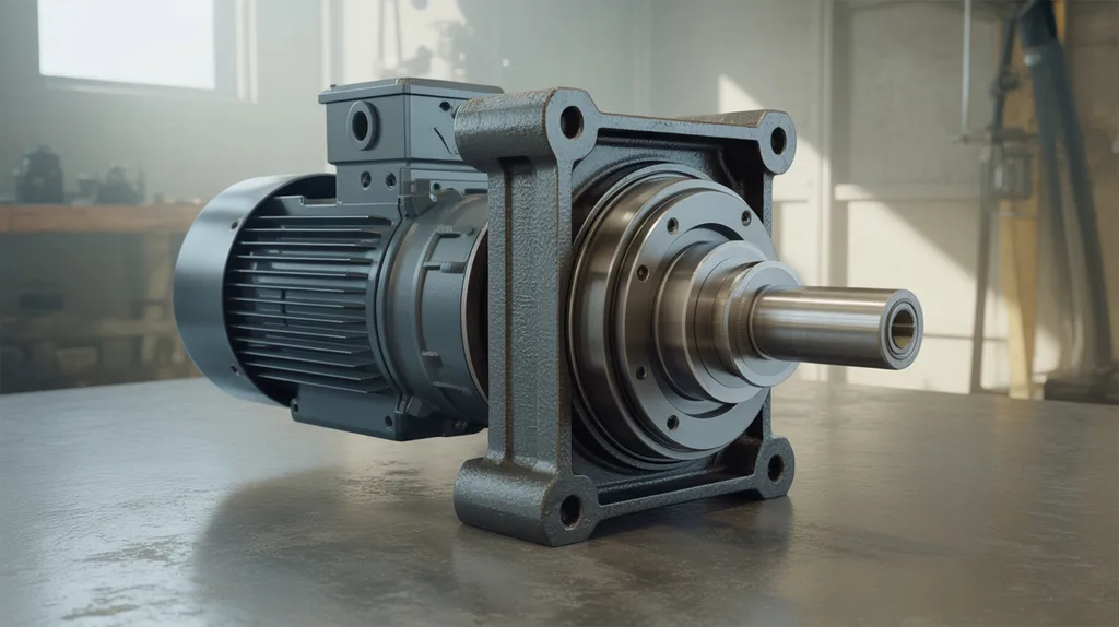
A gear motor’s size is the combination of its output torque, output speed, motor power, reduction ratio and physical dimensions. The correct selection must also match the load’s starting demand, duty cycle, power supply, mounting arrangement, shaft loads and operating environment.
Motor horsepower alone does not define whether a gear motor is suitable. Two motors with similar power can have different output speeds, torque ratings, gearbox ratios, mounting dimensions and starting capabilities.
| Sizing attribute | What it determines | Data to provide |
|---|---|---|
| Output speed | How fast the driven shaft turns | Machine speed, belt speed or shaft speed |
| Output torque | Whether the load can be moved or processed | Running, starting and breakaway torque |
| Motor power | Energy available to maintain torque and speed | Calculated power requirement |
| Reduction ratio | Relationship between motor speed and output speed | Motor RPM and required output RPM |
| Mechanical fit | Whether the unit can be installed | Mounting, shaft and envelope dimensions |
| Operating conditions | Thermal and environmental suitability | Duty, temperature, dust and moisture |
A practical gear reduction motor buying guide can help organize these requirements before requesting a quotation.
What Information Do I Need Before Sizing a Gear Motor?
Before sizing a gear motor, record the load, required output speed, running and starting torque, acceleration time, duty cycle, starts per hour, power supply, mounting arrangement and environment. For conveyors or inclined equipment, also record load weight, roller or pulley dimensions, incline angle and friction-related information.
Use this sequence to collect the application data:
- Identify the machine and load type.
- Record load mass, material and geometry.
- Specify the required output speed or acceptable speed range.
- Determine continuous running torque.
- Determine starting, breakaway and acceleration torque.
- Record the duty cycle and number of starts and stops per hour.
- Note incline, gravity load, friction and shock loading.
- Confirm voltage, phase, frequency and control method.
- Record mounting, shaft, radial-load and axial-load requirements.
- Describe temperature, dust, moisture and other environmental conditions.
Load weight, size, shape and friction all affect the torque and speed calculation. A conveyor calculation may additionally require belt speed, roller diameter, acceleration time and power-supply information.
How Do I Calculate the Required Output Speed?
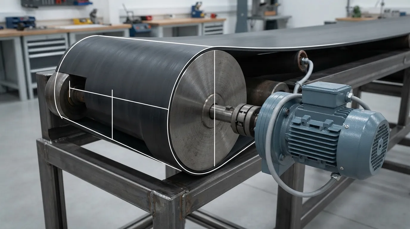
The required output speed is the speed of the driven machine’s shaft, not the motor’s unloaded speed. For a rotary machine, use the required shaft RPM. For a belt or roller system, convert linear speed and roller or pulley circumference into output RPM.
For a rotating shaft:
Required output speed = machine shaft speedFor a roller or pulley:
RPM = linear speed ÷ circumference × 60Use consistent units. If linear speed is expressed in inches per second, the circumference must also be in inches before applying the conversion to minutes.
According to Bodine Electric’s conveyor example, a belt speed of 12 inches per second and a four-inch roller produce a required roller speed of approximately 57.3 revolutions per minute. The example also specifies a 90-kilogram load, one-second acceleration and 115-volt alternating-current power.
The output speed calculation does not select the final gear motor by itself. The motor must still provide enough continuous and starting torque, and the reduction ratio must be available in a suitable gearbox.
How Do I Calculate the Torque a Gear Motor Needs?
Calculate the torque required at the output shaft during normal operation, then check the higher torque needed to start, accelerate or overcome breakaway friction. Include gravity torque when the load moves on an incline or vertically, and use the most demanding relevant condition for selection.
The main torque conditions are:
| Torque condition | When it matters | Selection implication |
|---|---|---|
| Continuous or running torque | The load is operating at steady speed | Determines sustained output capability |
| Friction torque | Bearings, seals, belts or product resistance oppose movement | Add resistance to the useful load torque |
| Breakaway torque | The load starts from rest | Check starting capability |
| Acceleration torque | The load must reach speed within a defined time | Depends on inertia and acceleration time |
| Gravity torque | The load moves uphill or vertically | Include incline and elevation effects |
| Shock torque | The load changes suddenly or may jam | Apply an appropriate service factor and verify limits |
For a general selection calculation:
Required design torque = governing load torque × service factorThe governing load torque may be the continuous, starting, acceleration or gravity torque, depending on the application.
According to Bodine Electric, conveyor sizing should consider friction torque, breakaway torque, acceleration torque and gravity torque. Bodine also notes that acceleration torque may be ignored only when acceleration time is not critical; it remains relevant when checking starting capability.
Gravity torque matters when a conveyor is inclined. It is zero for the horizontal conveyor in Bodine’s example, but an inclined or vertical application requires an additional calculation.
If friction or breakaway torque is uncertain, measurement can be more reliable than estimation. Practical methods described by Bodine include a string-and-pulley method, a torque-wrench method and a test-motor method.
For a deeper explanation of the equations and units, see this guide to gear motor torque speed calculation.
How Should I Apply a Service Factor?
A service factor allows for duty cycle, frequent starts and stops, shock loads, uncertain friction, acceleration and other demanding conditions. The factor must reflect the actual application and manufacturer guidance; it should not be treated as one fixed multiplier for every gear motor.
Consider these conditions when deciding how much allowance the application requires:
| Application condition | Why it changes sizing |
|---|---|
| Smooth, steady load | Has less variability, but continuous thermal capacity still matters |
| Frequent starts and stops | Raises starting and thermal demands |
| Short acceleration time | Increases acceleration torque |
| Inclined or vertical movement | Adds gravity torque |
| Impact or shock loading | Requires additional allowance and gearbox verification |
| Uncertain or changing load | May require measurement or a conservative engineering review |
Do not apply an unexplained, very large factor simply to avoid calculation. Excessive oversizing can increase cost, weight and energy use without correcting an incorrect gear ratio, unsuitable mounting arrangement or inadequate shaft-load rating.
Applications with frequent starts, shock loads or unusually high output torque may require a more detailed high torque gear motor selection review.
How Do I Calculate the Gear Ratio and Motor Power?
Calculate the reduction ratio from the motor speed and required output speed, then verify that the motor can provide the required output torque after gearbox losses and operating conditions are considered. Power is a useful cross-check, but torque and speed at the driven shaft remain the starting point.
The basic ratio relationship is:
Reduction ratio = motor speed ÷ required output speedFor example, a motor running at 1,500 RPM connected to a machine requiring 50 RPM would need a nominal reduction ratio of 30:1. The final selection must still be checked against the reducer’s available ratio, efficiency, load rating and operating conditions.
For imperial units, the retrieved Industrial Gearbox Supply guide gives this horsepower relationship:
HP = (Torque × RPM) ÷ 5252In this equation, torque is in pound-feet and speed is in revolutions per minute. Use the appropriate metric relationship when working in newton-metres and RPM, and state the units in the calculation.
| Selection question | What to verify |
|---|---|
| Is the output speed correct? | Rated output RPM under the actual load |
| Is continuous torque sufficient? | Continuous output torque and thermal capability |
| Can the drive start the load? | Starting and breakaway torque capability |
| Is the ratio practical? | Available reducer ratio and motor speed |
| Is motor power adequate? | Power after losses and duty-cycle considerations |
| Is the unit oversized? | Avoid unnecessary cost, weight and energy use |
A gear motor can have adequate horsepower but still be unsuitable if the output speed, starting torque, mounting or shaft-load requirements are wrong. For the motor-specific part of the calculation, see what size electric motor.
Which Motor and Gearbox Specifications Must I Confirm?
After calculating torque, speed and ratio, confirm motor voltage, phase, frequency, control method, duty rating, enclosure, mounting, shaft dimensions and allowable radial and axial loads. Choose the reducer type according to the application’s torque, speed, space, efficiency, backlash, backdriving and shock-load requirements.
| Specification group | Questions to confirm |
|---|---|
| Electrical | AC or DC? Single-phase or three-phase? What voltage, frequency and control method? |
| Duty | Continuous or intermittent? How many starts and stops per hour? |
| Mounting | Foot, flange, C-face, D-flange, vertical or custom mounting? |
| Shaft | What output shaft diameter, keyway and shaft arrangement are required? |
| External loads | What radial, axial or overhung loads act on the output shaft? |
| Environment | What temperature, dust, moisture and washdown conditions apply? |
| Gearbox behavior | What efficiency, backlash, backdriving and shock-load characteristics are required? |
| Installation constraints | What envelope, orientation, weight and service-access limits apply? |
Retrieved selection guidance identifies alternating-current, direct-current, servo and stepper motors as application-dependent categories. It also identifies foot mount, C-face, D-flange and vertical mounting as options that may need to be checked.
Does the reducer type affect sizing?
Reducer type affects efficiency, physical arrangement, allowable loads, backlash, backdriving behavior and suitability for shock or high-torque applications. Reducer type should therefore be chosen after the load and speed requirements are defined, not before.
For inline industrial drives, a helical geared motor may be one option to evaluate. A worm, planetary, cycloidal or other reducer may be more appropriate in different applications, but the correct choice depends on the complete specification.
Worked Example: Sizing the Speed Requirement for a Conveyor
A conveyor example shows why output speed and torque must be calculated separately. If a belt travels at 12 inches per second over a four-inch roller, the required roller speed is approximately 57.3 RPM. The final gear motor still requires a torque and duty check before a model can be selected.
According to Bodine Electric’s example, the stated conditions include:
- Load: 200 pounds, or approximately 90 kilograms
- Maximum belt speed: 12 inches per second
- Acceleration time: one second
- Roller diameter: four inches, or approximately 102 millimetres
- Power supply: 115-volt AC
- Calculated roller speed: approximately 57.3 RPM
Apply the sizing process as follows:
- Record the belt speed and roller diameter.
- Convert the linear belt speed to roller RPM.
- Identify whether the conveyor is horizontal or inclined.
- Determine running, friction, breakaway and acceleration torque.
- Apply a service factor appropriate to the duty and shock conditions.
- Calculate the required reduction ratio.
- Verify motor power, voltage, duty and mounting.
- Compare the resulting requirements with the manufacturer’s rating tables.
This example demonstrates the speed calculation only. It does not establish a universal motor size because the complete torque, friction, duty and shaft-load data must also be known.
What Should I Send a Gear-Motor Supplier?
Send the supplier the required output RPM, continuous and peak torque, load and machine details, duty cycle, starts per hour, acceleration time, power supply, mounting dimensions, shaft loads, environment and control requirements. Complete data allows the motor, reducer ratio and physical fit to be evaluated together.
Provide the following information:
- Application or machine type
- Load mass, product characteristics and load distribution
- Required output speed and acceptable speed range
- Continuous running torque
- Starting, breakaway and peak torque
- Acceleration time and inertia information
- Incline, vertical movement or gravity load
- Duty cycle and operating hours
- Starts and stops per hour
- Shock, impact, jam or overload conditions
- Voltage, phase, frequency and control system
- Mounting style, orientation and available envelope
- Output shaft dimensions and coupling details
- Radial and axial shaft loads
- Ambient temperature, dust, moisture and washdown conditions
- Required mounting or transmission-ratio customization
Mingye designs and supplies industrial motors and reducers, manufactures both in its own CNC-equipped factory, and offers OEM customization of mounting dimensions and transmission ratios. Those capabilities can be relevant when a standard mounting arrangement or ratio does not match the machine design.
What Are the Most Common Gear-Motor Sizing Mistakes?
The most common errors are choosing by horsepower alone, ignoring breakaway torque, omitting acceleration or incline loads, using an arbitrary service factor, and failing to check mounting or shaft loads. A gear motor that runs a machine at no load may still fail to start it reliably or withstand its duty cycle.
Avoid these mistakes:
- Selecting by motor wattage or horsepower alone.
- Using normal running torque as the starting requirement.
- Ignoring friction, breakaway or acceleration.
- Omitting gravity torque on inclined or vertical equipment.
- Applying an unexplained universal service factor.
- Ignoring duty cycle and starts per hour.
- Forgetting voltage, phase or control compatibility.
- Checking motor dimensions but not gearbox mounting and shaft loads.
- Selecting a reducer type before defining the load.
- Treating a worked example as a final model recommendation.
How Do I Know the Selected Gear Motor Is Adequate?
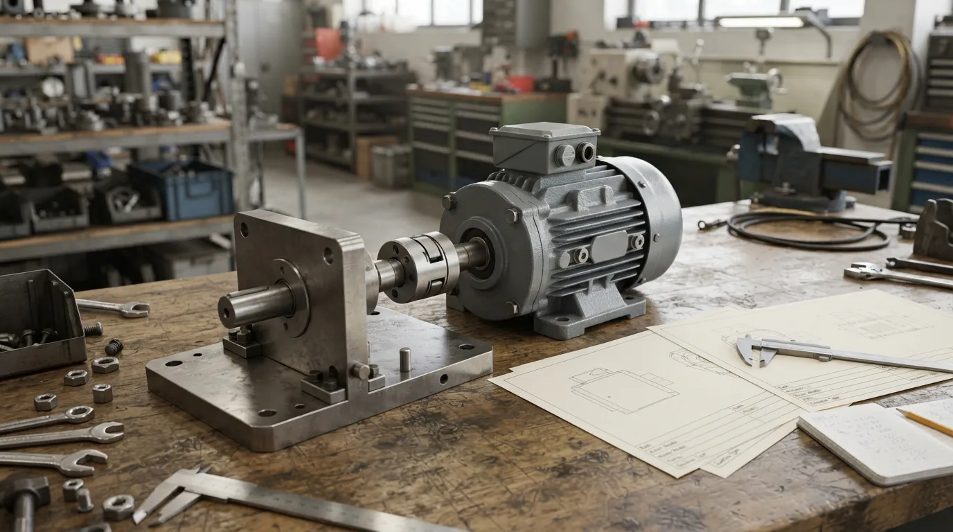
A gear motor selection is adequate only when its rated output speed, continuous torque, starting capability, duty rating, motor power, ratio, mounting, shaft-load limits and environmental suitability all match the application. Review the manufacturer’s rating data and confirm uncertain load values through measurement or supplier engineering review.
| Verification | Pass condition |
|---|---|
| Output speed | Meets the required machine speed under load |
| Continuous torque | Exceeds sustained operating torque |
| Starting torque | Handles breakaway and acceleration demand |
| Service factor | Reflects actual duty and shock conditions |
| Motor power | Supports torque and speed after losses |
| Gear ratio | Produces the required output RPM |
| Mounting and shaft | Fits mechanically and handles external loads |
| Electrical supply | Matches voltage, phase, frequency and controls |
| Environment | Suits temperature, dust and moisture conditions |
| Documentation | Records ratings, assumptions and selection data |
Frequently Asked Questions
How Do I Decide What Motor Size I Need?
Motor size follows the required output torque and speed, not load weight alone. The calculation must also include starting demand, duty cycle, service factor, gear ratio, power supply and mounting constraints. A supplier needs these details to confirm whether a particular motor and reducer combination can operate reliably.
Is a Higher-Horsepower Gear Motor Always Better?
A larger motor is not automatically better. Oversizing can increase cost, physical size and energy use while failing to solve an incorrect ratio, mounting issue or shaft-load problem. The correct choice is a properly rated unit that satisfies torque, speed, duty and starting requirements with suitable application-specific allowance.
What Do S1, S2, S3 and S4 Motor Duties Mean?
S1, S2, S3 and S4 are motor-duty classifications describing operating-cycle conditions such as continuous operation, short-time operation, intermittent operation and starting-related duty. Duty classification affects thermal sizing and must match the actual run, rest and starting pattern. It does not replace torque, speed or temperature checks.
Which Gear Motor Is Best?
There is no universally best gear motor. The appropriate choice depends on required torque, speed, ratio, duty cycle, shock, mounting, environment, backlash, backdriving and shaft-load requirements. Compare reducer types only after defining the application data, rather than choosing from motor size or brand name alone.
If you have the required torque, speed, duty, mounting and power-supply data, Mingye can review the application and discuss an industrial gear-motor configuration, including OEM mounting-dimension or transmission-ratio requirements.
Share on Social:


Contact Us
In This Article
Right Angle Geared Motor: Matching Electrical Supply, Variable Speed and Braking
Oct 26, 2026
Planning a Bevel Reducer Installation: Turn Shaft Requirements Into a Practical Drive Layout
Oct 26, 2026
Choosing an Overhead Crane Gearbox by Its Hoisting or Travel Function
Oct 26, 2026
Replacing an Industrial Worm Gearbox: What to Keep and What to Reassess
Oct 25, 2026