


 Home /
How to Choose a Cycloidal Gear Reducer?
Vertical-Axis Drives After Power Loss: Which Holding and Brake Data Must OEMs Verify?
Oct 14, 2026
Indexing Packaging Machines: Calculating Acceleration Torque From a Motion Profile
Oct 14, 2026

Changing an NMRV Worm Gearbox Ratio: Can You Keep the Existing Motor?
Oct 14, 2026
How to Check Overhung Load When a Chain Sprocket Is Moved Along a Gearbox Output Shaft
Oct 14, 2026
Choose a cycloidal gear reducer by output torque, reduction ratio, shock-load level, mounting configuration, and duty cycle — then confirm the service factor. Start with the driven load's torque requirement, not the gearbox. Industrial pin-wheel units handle heavy shock (up to 500% momentary overload); precision robotic cycloidal units prioritize low backlash. Match the topology to the application before sizing the unit.
Key Takeaways
- Select by output torque, ratio, shock-load level, mounting, and duty cycle, then confirm the service factor — never below 1.0.
- Cycloidal drives absorb shock loads up to 500% of rated torque without tooth breakage, beating planetary units in shock-prone applications.
- Single-stage cycloidal reducers deliver ratios from 10:1 to 200:1 at 85–93% efficiency.
- Industrial pin-wheel units tolerate moderate backlash; precision robotic cycloidal units target near-zero backlash for articulated joints.
- Thermal rating matters: continuous-duty units must not exceed ambient temperature by more than approximately 40°C at 100% load.
What Is a Cycloidal Gear Reducer?
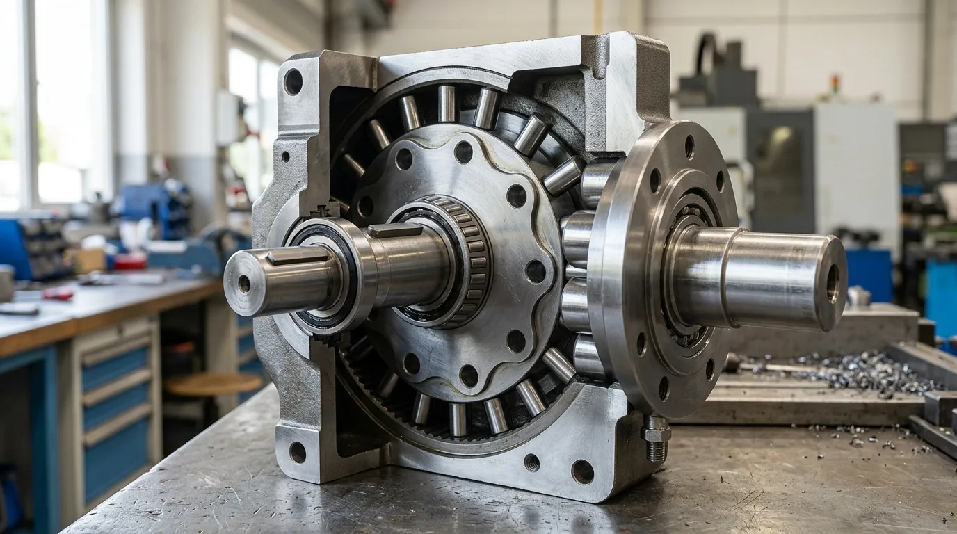
A cycloidal gear reducer is a compact, high-torque speed reducer that uses an eccentric cam to roll a lobed cycloidal disc inside a ring of pins, converting input speed into output torque with a large reduction in a single stage. Instead of meshing teeth, the mechanism relies on rolling contact between the disc lobes and ring pins. According to Firgelli Automations, at any moment 60–70% of the lobes are sharing load simultaneously, which spreads stress and makes the design exceptionally resistant to shock.
The key components are the lobed cycloidal disc, the eccentric shaft (or cam), the ring pins fixed to the housing, and the output rollers that capture the disc's orbital motion. Because the disc is always in rolling contact rather than sliding contact, the unit stays compact while delivering high torque density. Disc face hardness typically runs 58–62 HRC to withstand the Hertzian contact stress at the pin interface, according to Firgelli Automations.
Cycloidal vs. Other Reducer Types: When Does Each Win?
Cycloidal reducers win when you need high shock tolerance, compactness, and low backlash in a single stage. Planetary reducers win for precision at high speeds. Worm gearboxes win for right-angle, low-cost applications where efficiency is secondary. Harmonic drives win for extreme precision at low torque in robotic and optical systems.
| Parameter | Cycloidal | Planetary | Worm | Harmonic |
|---|---|---|---|---|
| Efficiency (single stage) | 85–93% | up to 97% | 60–85% | 60–80% |
| Shock tolerance (% rated torque) | up to 500% | ~250–300% | moderate | low |
| Backlash | 1–30 arcmin (industrial) | 3–20 arcmin | 10–60 arcmin | <1 arcmin |
| Ratios (single stage) | 10:1–200:1 | 3:1–100:1 | 5:1–100:1 | 50:1–320:1 |
| Typical applications | Mixers, conveyors, crushers, robotics | Servo axes, machine tools | Right-angle, simple drives | Robotics joints, optics |
Efficiency is a key differentiator. According to Firgelli Automations, cycloidal drives run at 85–93% efficiency — well above a worm gear at the same ratio. Tanhon reports worm gear reducers range from 60–85% efficient depending on the reduction ratio, while helical gear reducers typically exceed 95% efficiency per gear stage. If energy cost per hour matters for your installation, the efficiency gap between cycloidal and worm units gets reflected in your electricity bill. For a deeper comparison, see planetary vs cycloidal gearbox or the cycloidal vs worm gearbox breakdown.
The 6-Step Cycloidal Reducer Selection Process

The selection process has six steps: calculate load torque, apply a service factor, match the ratio, verify shock-load tolerance, confirm mounting and envelope, and check the thermal rating for continuous duty. Follow them in order — skipping the service factor is the most common specification error.
Step 1 — Calculate Required Output Torque
Output torque = (Power in kW × 9550) ÷ Output speed (RPM), then correct for drive efficiency and starting conditions. The 9550 factor converts kilowatts and RPM into newton-meters (Nm).
5.5 × 9550 × 0.90 ÷ 30 ≈ 1,576 Nm of required output torque
This is steady-state torque. You will need the peak torque value for the shock-load check in Step 4. For applications with especially high torque demands, review the details on cycloidal gearbox high torque configurations.
Step 2 — Apply the Service Factor
Multiply the calculated torque by a service factor — 1.0 for uniform load, up to 3.0 or higher for heavy shock — and always use a value of at least 1.0. According to Tanhon, a value below 1.0 is never valid. The service factor is a safety margin that accounts for load variability, starting torque, and application severity.
| Application / Load Type | Service Factor |
|---|---|
| Uniform load (conveyors, packaging) | 1.0–1.25 |
| Moderate shock (mixers, agitators) | 1.5–1.75 |
| Heavy shock (crushers, mills) | 2.0–3.0+ |
A uniformly loaded conveyor may need a service factor of only 1.0, while a rock crusher with shock loading should run at 3.0 or higher, according to Tanhon. When in doubt, choose the higher factor — the cost of an oversized unit is small compared with the cost of an undersized unit failing in service.
Step 3 — Match the Reduction Ratio
Match the ratio to the required output speed. Single-stage cycloidal units cover 10:1 to 200:1, so most industrial needs are met without multiple stages, according to Firgelli Automations. The ratio determines how many times the input shaft must rotate to produce one full output revolution.
To select the ratio, divide the input motor speed by the desired output speed. For example, a 1,450 RPM motor driving a 29 RPM output requires a 50:1 ratio. If your calculated ratio falls outside the single-stage range, consider a two-stage unit or a different reducer topology. For ratio-specific guidance, including how to handle fractional ratios, see our guide on cycloidal reducer gear ratio.
Step 4 — Verify Shock-Load Tolerance
Confirm the unit can absorb momentary peak loads — cycloidal drives tolerate up to 500% of rated torque momentarily, according to Firgelli Automations. Compare this against your worst-case peak torque from Step 1, not the steady-state value.
It is commonly cited that a cycloidal box can sustain approximately 300% momentary overload, whereas a typical spur gear planetary can sustain only about 250% (community-sourced, lower authority). This difference matters in applications with frequent starts, stops, or jam events. If your peak load exceeds the unit's momentary capacity, select a larger unit rather than relying on the service factor alone.
Step 5 — Confirm Mounting and Envelope
Choose foot-mounted, flange-mounted, or hollow-shaft configurations based on the driven machine's interface, and verify the envelope fits the installation space. Each mounting type serves a different purpose:
- Foot-mounted: Simplest installation; best for floor or frame mounting where the output shaft aligns horizontally.
- Flange-mounted: Compact; bolts directly to the driven machine, saving space and eliminating alignment issues.
- Hollow-shaft: Slides directly onto the driven shaft; ideal for retrofits and space-constrained installations.
Also verify the overhung load — the radial force applied at the shaft extension — does not exceed the unit's rated capacity. Overhung loads are a common cause of premature bearing failure, yet they are frequently overlooked during selection.
Step 6 — Check Thermal Rating for Continuous Duty
For continuous duty, verify the unit's thermal rating: a cycloidal reducer at 100% load in S1 duty should not exceed approximately 40°C over the ambient temperature. According to Cone Drive, rated torque should not cause the unit to exceed 25°C ambient by more than 40°C in S1 (continuous) duty. Manufacture-specific lifetime ratings — such as Cone Drive's stated L10 of 6,000 hours at 100% duty factor — also help qualify a candidate unit.
If your application runs continuously at high load, the thermal limit may force you to select a physically larger unit than the torque calculation alone would suggest. Heat is the enemy of lubricant life and seal integrity; a unit that is thermally marginal will fail long before the gears wear out.
Industrial vs. Precision Cycloidal Units: Which Do You Need?
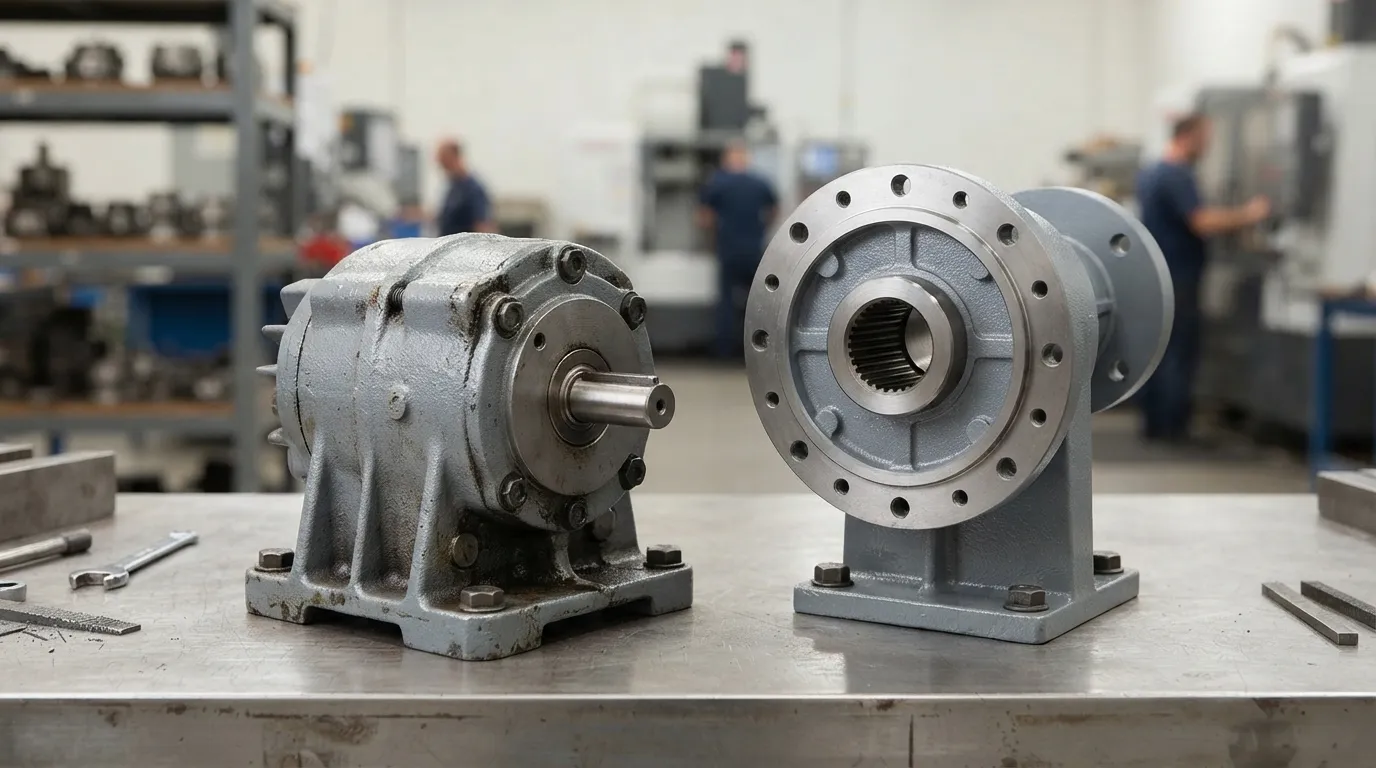
If your application tolerates 5–30 arcmin backlash and you need shock tolerance, an industrial pin-wheel unit is sufficient. If you build a robot joint or indexer requiring under 1 arcmin backlash, choose a precision RV-type cycloidal unit. These are different product families, not different grades of the same unit.
| Criteria | Industrial Pin-Wheel | Precision (RV-type) |
|---|---|---|
| Backlash | 5–30 arcmin | <1 arcmin |
| Shock tolerance | High (up to 500%) | Moderate |
| Cost | Lower per Nm | Higher |
| Applications | Conveyors, mixers, crushers | Robot joints, indexers |
| Typical maintenance | Low | Low, careful follow-up |
Industrial pin-wheel units prioritize torque density and shock absorption at a reasonable cost. Precision RV-type units add an internal planetary pre-stage to reduce backlash and improve positioning accuracy for servo-driven robotic applications. The extra complexity and tighter tolerances explain the higher price per Nm. Choosing a precision unit for a mixer or conveyor is wasted capability; choosing an industrial unit for a robot joint will result in unacceptable positioning error.
Common Mistakes When Selecting a Cycloidal Reducer
The most common mistakes are sizing on nameplate power instead of peak torque, ignoring thermal limits on continuous duty, neglecting overhung load, choosing precision grade when industrial grade suffices, and skipping the service factor. Avoid them and the selection process becomes straightforward.
- Sizing on nameplate power instead of peak torque. Nameplate power reflects steady-state rating, not the starting or jam torque that the unit will actually experience.
- Ignoring thermal limits on continuous duty. A unit sized only for torque can overheat when run at 100% load around the clock.
- Neglecting overhung load. Radial forces from sprockets, pulleys, or pinions shorten bearing life if they exceed the rated capacity.
- Choosing precision grade when industrial grade suffices. You pay a significant premium for sub-arcmin backlash you may never use.
- Skipping the service factor. A value of 1.0 is a minimum, not a recommendation — always match it to the application severity.
Selection Checklist Before You Contact a Supplier
Complete these six items before requesting a quote. A well-specified inquiry gets a faster, more accurate response from any supplier.
- [ ] Required output torque (steady state), in Nm
- [ ] Service factor selected for the application type
- [ ] Reduction ratio (input speed ÷ output speed)
- [ ] Peak/shock torque and frequency of shock events
- [ ] Mounting type (foot, flange, hollow shaft) and envelope dimensions
- [ ] Duty cycle (continuous S1, intermittent S2–S8, or cyclic)
Cycloidal Reducer Applications
Cycloidal reducers serve conveyors, mixers, packaging lines, welding rotators, and rubber or plastic machinery where compactness and shock tolerance matter. They are especially valuable where space is tight and momentary overloads are common — conditions that would damage a planetary or worm unit of the same size. For a full review of where cycloidal units perform best, see our breakdown of cycloidal gearbox applications.
Mingye's Approach to Cycloidal Reducer Supply
Mingye designs and builds cycloidal pinwheel reducers as part of a range covering more than 20 series of industrial power transmission equipment. All units are manufactured in the company's own CNC-equipped factory in Shanghai on modular, standardized designs, which allows OEM customization of mounting dimensions and transmission ratios. Typical delivery runs 7–15 days, and Mingye serves OEMs and plant engineers across plastics and rubber, mixing, conveying, packaging, mining, cement, power, and port industries.
If you are comparing unit costs across suppliers, see our overview of industrial gearbox price considerations before requesting quotes. A properly specified cycloidal reducer — selected by output torque, ratio, shock-load level, mounting, and duty cycle, with the service factor confirmed — will perform reliably for years at a predictable cost.
Share on Social:


Contact Us
In This Article
Vertical-Axis Drives After Power Loss: Which Holding and Brake Data Must OEMs Verify?
Oct 14, 2026
Indexing Packaging Machines: Calculating Acceleration Torque From a Motion Profile
Oct 14, 2026
Changing an NMRV Worm Gearbox Ratio: Can You Keep the Existing Motor?
Oct 14, 2026
How to Check Overhung Load When a Chain Sprocket Is Moved Along a Gearbox Output Shaft
Oct 14, 2026