


 Home /
Inline Gearbox vs Right Angle Gearbox: Which Design Fits Your Machine?
Vertical-Axis Drives After Power Loss: Which Holding and Brake Data Must OEMs Verify?
Oct 14, 2026
Indexing Packaging Machines: Calculating Acceleration Torque From a Motion Profile
Oct 14, 2026

Changing an NMRV Worm Gearbox Ratio: Can You Keep the Existing Motor?
Oct 14, 2026
How to Check Overhung Load When a Chain Sprocket Is Moved Along a Gearbox Output Shaft
Oct 14, 2026
An inline gearbox is usually the better fit when the motor and driven shaft can remain on the same centerline and efficiency or straightforward alignment is important. A right-angle gearbox is preferable when the machine needs a 90-degree power-direction change, shorter axial length or side-mounted motor. The final choice depends on space, gear technology, loads, duty cycle and maintenance access.
Inline gearbox vs right-angle gearbox: What is the difference?
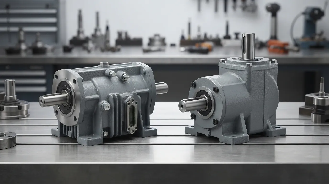
An inline gearbox keeps its input and output shafts on the same axis. A right-angle gearbox places the shafts at approximately 90 degrees, changing the direction of power through the drivetrain.
The difference is primarily geometric, but geometry is not the only selection factor. A right-angle gearbox may use bevel, helical-bevel, hypoid, worm or planetary gearing. These internal gear technologies can have different efficiency, ratio, load, heat and maintenance characteristics.
| Criterion | Inline gearbox | Right-angle gearbox |
|---|---|---|
| Shaft arrangement | Input and output shafts share the same axis | Input and output shafts are arranged approximately 90 degrees apart |
| Main layout benefit | Supports a straight drivetrain | Changes power direction and can support side-mounted layouts |
| Typical space trade-off | May require more axial room | May reduce axial length but require radial or side clearance |
| Efficiency | Often favourable with suitable helical gearing | Depends strongly on the internal gear technology |
| Main selection question | Can the drive remain straight? | Does the machine require a directional change? |
| Common design check | Axial installation and removal space | Side clearance, mounting orientation and angled-drive access |
The terms “inline” and “right angle” should therefore not be treated as complete gearbox specifications. A correct comparison also needs the required ratio, input speed, output speed, torque, external loads, duty cycle and operating environment.
What is an inline gearbox?
An inline gearbox, also called a coaxial gearbox when the shafts share the same centerline, places the motor input and gearbox output in a straight transmission path. The arrangement suits machines where the motor and driven equipment can be aligned and sufficient axial space is available.
An inline gearbox can simplify a straight-line coupling and mounting arrangement. However, an inline design is not automatically the shortest or smallest option: the motor, reducer, coupling, guard and service area all contribute to the machine envelope.
When does an inline gearbox make sense?
An inline gearbox makes sense when the motor and driven shaft can remain on one centerline, axial space is available and a straight transmission path supports the machine layout.
Typical starting points include:
- Straight conveyor drives.
- Material-handling equipment with an aligned drive path.
- Machine axes where motor and output alignment is practical.
- OEM equipment designed around a coaxial motor-reducer package.
- Machinery where a direct coupling path simplifies installation.
For readers comparing broader helical drive arrangements, Mingye’s helical geared motor range provides a relevant product category to examine alongside the layout decision.
An inline gearbox still requires application-specific sizing. The same shaft arrangement can be used in machines with very different speeds, ratios, loads and duty cycles.
What is a right-angle gearbox?
A right-angle gearbox positions the input and output shafts at approximately 90 degrees. This arrangement allows the motor and driven equipment to sit in different directions and can help when axial length is restricted or side mounting is preferred.
A right-angle gearbox is defined by shaft geometry, not by one specific gearset. Bevel, worm, hypoid, helical-bevel and planetary configurations can all be used for right-angle transmission, depending on the required performance and machine layout.
Right-angle gearboxes can also introduce axial and radial forces that must be absorbed by bearings. Neugart identifies these forces as one factor that can contribute to efficiency losses, so the shaft arrangement and external-load conditions should be reviewed together.
Does a right-angle gearbox always use worm gears?
No. A right-angle gearbox does not always use worm gears. “Right angle” describes the relationship between the input and output shafts, while the internal gearset may be bevel, helical-bevel, hypoid, worm or planetary.
The gear technology affects the gearbox’s efficiency, reduction capability, heat generation, wear behaviour, noise, backlash and maintenance requirements. Comparing an inline helical gearbox with a right-angle worm gearbox is therefore a comparison of both shaft arrangement and gear technology.
Inline vs right-angle gearbox: Space and machine layout
Inline gearboxes preserve a straight transmission path but can require more axial room for the motor and reducer. Right-angle gearboxes can shorten the drive in the motor-to-output direction, but they need adequate side or radial clearance around the turned drivetrain.
The correct question is not simply “Which gearbox is smaller?” It is “Where does the machine have usable space, and where must operators access the drive?”
| Layout question | Inline choice | Right-angle choice |
|---|---|---|
| Is axial space available? | Usually favourable when the drive can extend along the shaft axis | Useful when motor-to-output length is restricted |
| Is side clearance available? | May require less side offset | Required for the changed shaft direction and housing |
| Can the motor stay on the output centerline? | Yes | Usually no; the geometry changes the motor position |
| Is a straight coupling path preferred? | Yes | No; the power direction changes |
| Is motor removal possible? | Check the axial extraction path | Check the side, top and output-side extraction paths |
| Are service openings accessible? | Check access along the drive axis | Check access around the angled assembly |
A right-angle gearbox may reduce axial length without reducing the total machine footprint. The motor, housing, coupling, guards and maintenance clearance still need to fit within the equipment envelope.
[DIAGRAM: Side-by-side technical view of a coaxial inline gearbox and a right-angle gearbox, with input shaft, output shaft, axial clearance and radial clearance labelled.]
A related layout decision is whether the machine needs coaxial shafts or offset parallel shafts. Engineers comparing those arrangements can review parallel shaft vs right angle gearbox before finalizing the transmission geometry.
Which gearbox is more efficient: Inline or right angle?
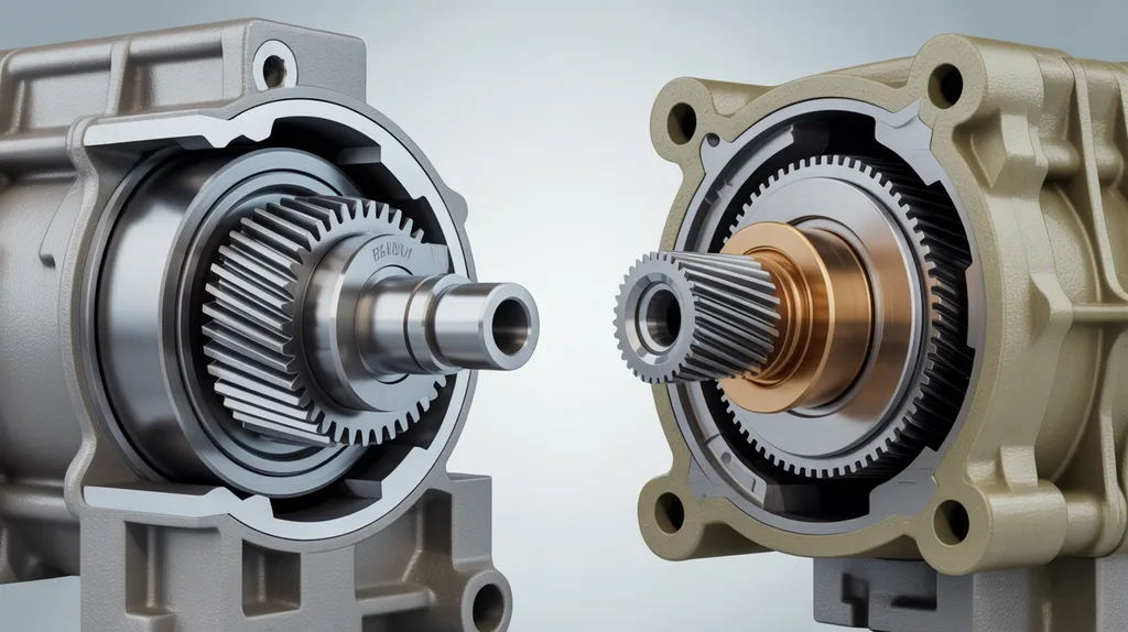
An inline gearbox is often efficient when it uses suitable helical gearing and operates within its design conditions, but a right-angle gearbox is not inherently inefficient. Efficiency depends on the internal gear technology, reduction ratio, speed, load, lubrication and duty cycle.
According to JIE, examples include more than 95% for some inline helical gearboxes, approximately 85–90% for bevel gears and approximately 70–80% for worm gears. These are source-specific examples, not universal ratings for every inline or right-angle gearbox.
GAM describes spiral bevel gearing as highly efficient because its tooth contact is mainly rolling. The same source describes worm gearing as having more sliding action and lower relative mechanical efficiency, while also noting its high reduction capability and torque throughput.
| Efficiency factor | Why it matters |
|---|---|
| Gear technology | Helical, bevel, hypoid, worm and planetary arrangements have different meshing behaviour |
| Reduction ratio | Higher reductions may require different gear arrangements or additional stages |
| Load and speed | The operating point affects losses and heat |
| Lubrication | Correct lubrication supports the intended operating conditions |
| Duty cycle | Continuous operation creates different thermal demands from intermittent duty |
| Shaft loads | Radial, axial and overhung loads affect bearings and drivetrain behaviour |
| Temperature control | Heat must be managed within the gearbox’s specified operating conditions |
The practical conclusion is that “inline versus right angle” is not a sufficient efficiency comparison. Compare the actual gearbox technologies under the required speed, ratio, load and operating cycle.
For a more focused comparison of helical and worm technologies, see helical vs worm gearbox.
How do mounting, alignment and maintenance access compare?
Inline gearboxes usually support a straight shaft and coupling layout, but the motor, coupling and gearbox may need access along the drive axis. Right-angle gearboxes can provide more flexibility in motor placement, but the angled drivetrain requires careful checks around mounting, alignment, lubrication and service access.
| Installation or maintenance issue | Inline gearbox | Right-angle gearbox |
|---|---|---|
| Coupling alignment | Straight-line alignment | Alignment across a directional change |
| Motor removal | Check the axial extraction path | Check side or top extraction access |
| Lubrication access | Confirm ports and mounting orientation | Confirm ports, orientation and gearset requirements |
| Bearing loads | Check output overhung and axial loads | Check forces associated with the angle drive and external loads |
| Inspection clearance | Usually along the drive axis | Often around the side-mounted or angled assembly |
| Guarding | Protect the straight coupling and rotating shafts | Protect the angled coupling, shafts and housing interfaces |
| Replacement access | Leave room to withdraw the motor-reducer assembly | Leave room around the motor and right-angle housing |
Maintenance access should be planned before the gearbox is installed. A compact layout can become difficult to service if the motor cannot be removed, lubrication points are blocked or inspection covers cannot be reached.
Use this installation check:
- Mark the input and output shaft centerlines on the machine layout.
- Confirm axial, radial and vertical clearance around the gearbox and motor.
- Check the mounting face, foot, flange and shaft interfaces.
- Verify coupling, guard and motor-removal access.
- Confirm lubrication orientation and inspection access.
- Check external radial, axial and overhung loads against the selected gearbox documentation.
How do torque, speed, ratio and load affect the choice?
Shaft arrangement is only the first selection filter. The gearbox must also match input speed, output speed, transmission ratio, torque, duty cycle and external loads.
W.C. Branham identifies input and output torque, revolutions per minute, desired gear ratio, duty cycle and overhung, axial or external moment loads as gearbox-selection factors. These requirements can influence both the gearbox size and the suitability of a particular gear technology.
Check the following before choosing between inline and right-angle designs:
- Required output speed.
- Required transmission ratio.
- Motor power and input speed.
- Continuous or intermittent duty.
- Starting, stopping and shock-load conditions.
- Output torque and the manufacturer’s sizing method.
- Radial, axial, overhung and moment loads.
- Mounting orientation and shaft interfaces.
- Ambient temperature, dust, moisture, washdown and corrosion exposure.
- Available inspection, lubrication and replacement access.
Environmental conditions can also affect the specification. W.C. Branham identifies extreme temperature, shock, vibration, washdown and corrosion exposure as conditions that may require attention to materials or coatings.
A right-angle design should not be selected only because it fits into a shorter axial envelope. A gearbox that fits physically but cannot handle the external load, duty cycle or environment is not a suitable machine solution.
Which applications suit inline and right-angle gearboxes?
Inline gearboxes commonly suit machines with a straight drive path, while right-angle gearboxes suit equipment where the motor must sit beside the driven shaft or where the power path must turn.
The following examples are starting points, not universal rules:
| Machine condition | Likely starting point | Reason to verify |
|---|---|---|
| Straight conveyor drive with axial space | Inline gearbox | Confirm output load, speed and mounting |
| Conveyor with restricted rear length | Right-angle gearbox | Confirm side clearance and output load |
| Mixer or paddle drive needing a side-mounted motor | Right-angle gearbox | Confirm torque, duty cycle and shaft loads |
| Packaging machine with a compact directional layout | Right-angle gearbox | Confirm speed, backlash and service access |
| OEM machine with aligned motor and output | Inline gearbox | Confirm the complete axial installation envelope |
| Heavy-duty material-handling or mining equipment | Either, depending on the application | Verify torque, shock, environment and service requirements |
A conveyor motor gearbox may be relevant for conveyor applications, but the final arrangement still depends on the conveyor’s drive position, available clearance, belt or chain loads and required output speed.
Mixers, paddle mixers, plastics machinery and rubber-processing equipment may have demanding duty cycles or external loads. These applications should be evaluated from the complete operating profile rather than selected by shaft angle alone.
How should you choose between an inline and right-angle gearbox?
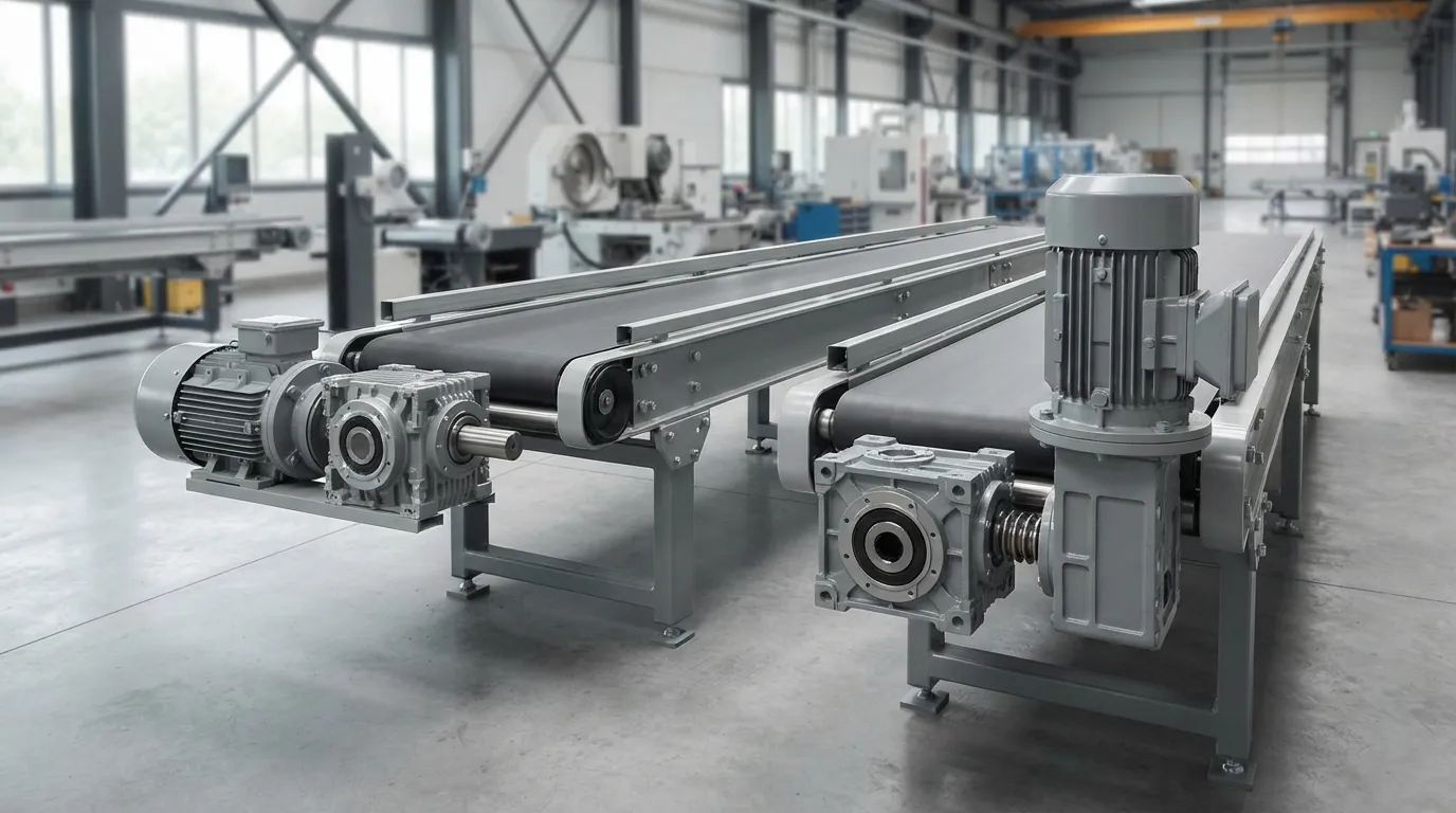
Choose an inline gearbox when the machine can use a straight centerline and the required axial space is available. Choose a right-angle gearbox when the drivetrain must turn, the motor needs side placement or axial length is restricted.
Use this decision process:
- Draw the required power path. Decide whether the input and output must remain on the same axis or meet at approximately 90 degrees.
- Measure the machine envelope. Record axial length, side clearance, height and the space required for guards and service.
- Define operating requirements. Specify motor power, input speed, output speed, ratio and required torque.
- Identify external loads. Check radial, axial, overhung and moment loads at the output shaft.
- Select the gear technology. Compare helical, bevel, helical-bevel, worm, hypoid or planetary options where applicable.
- Check duty and environment. Include continuous operation, shock, vibration, dust, moisture, washdown and temperature.
- Verify mounting and maintenance. Confirm the flange, foot, shaft, lubrication, inspection and replacement arrangements.
- Confirm OEM interfaces. Check mounting dimensions, shaft dimensions and any required customized transmission ratio.
An inline helical gearbox and a parallel-shaft helical gearbox are related but distinct layout options. If the machine requires offset shafts rather than coaxial shafts, review the parallel shaft helical gearbox configuration separately.
How do Mingye’s R, K and S series fit this comparison?
Mingye’s range provides OEMs and plant engineers with starting points for both layout types: the R series can be considered for inline helical applications, while K and S series options can be considered where a right-angle power path is required. Final selection should be based on the machine’s verified dimensions, ratio, speed, torque, loads and duty cycle.
Mingye designs and manufactures industrial power-transmission equipment, including R, S and K series helical gear motors. The company builds motors and reducers in its own CNC-equipped factory using modular, standardized designs.
Mingye also offers OEM customization of mounting dimensions and transmission ratios. That can be relevant when an existing machine envelope, shaft position or replacement interface limits the available gearbox arrangement.
For readers evaluating the S-series product family, the S series helical worm gear motor is a relevant product path to review. Product-specific efficiency, torque, ratio, dimensions and load limits should be confirmed from the applicable technical documentation rather than inferred from the series name.
Mingye normally delivers in 7–15 days and serves OEMs and plant engineers in conveying, material handling, mixing, packaging, plastics and rubber, mining, cement, power and ports. Delivery timing and product suitability remain application- and order-dependent.
Final decision: Inline or right angle?
Select an inline gearbox when the machine can use a straight centerline, axial space is available and a direct transmission path supports installation and maintenance. Select a right-angle gearbox when the drivetrain must change direction, the motor needs side placement or axial length is limited.
Choose an inline gearbox when:
- The motor and driven shaft can remain aligned.
- Axial installation space is available.
- A straight coupling path simplifies the machine.
- The application suits an inline gear technology and load range.
- Motor and gearbox removal can be performed along the available axis.
Choose a right-angle gearbox when:
- The power path must turn approximately 90 degrees.
- The motor needs to sit beside the driven shaft.
- Rear or axial machine length is restricted.
- Side clearance and angled-drive maintenance access are available.
- The selected bevel, helical-bevel, worm, hypoid or planetary technology matches the operating requirements.
For an OEM or plant application, provide the mounting dimensions, desired transmission ratio, motor power, input and output speed, torque, duty cycle, external loads and operating environment. Mingye can use those requirements to evaluate a suitable industrial power-transmission configuration.
Frequently asked questions
Does a right-angle gearbox always use a worm gear?
No. A right-angle gearbox describes the input and output shaft arrangement, not one specific gearset. Bevel, helical-bevel, hypoid, worm and planetary gearsets can all be used. The selected technology affects efficiency, ratio capability, load behaviour, heat generation, wear and maintenance requirements.
Is an inline gearbox always more efficient than a right-angle gearbox?
No. Efficiency depends on the internal gearset, ratio, speed, load, lubrication and duty cycle. Inline helical designs may be highly efficient, while right-angle bevel or helical-bevel designs can also perform efficiently. Worm designs generally involve more sliding, but the complete application still determines suitability.
What is a 90-degree gearbox called?
A 90-degree gearbox is usually called a right-angle gearbox or right-angle gear reducer. The term describes the approximate angle between the input and output shafts. It does not identify whether the gearbox uses bevel, helical-bevel, worm, hypoid, planetary or another internal gear arrangement.
Which gearbox is better for a conveyor?
Either arrangement may be suitable. An inline gearbox fits a conveyor with an aligned drive path and available axial space. A right-angle gearbox may suit a conveyor with restricted rear length or a side-mounted motor. Final selection requires checks for speed, torque, external loads, duty cycle and mounting.
Can a right-angle gearbox save space?
A right-angle gearbox can reduce the axial length required between the motor and output shaft when the machine uses a side-mounted layout. It does not eliminate the need for space: the housing, motor, guards, radial clearance and maintenance access must still fit within the equipment envelope.
Share on Social:


Contact Us
In This Article
Vertical-Axis Drives After Power Loss: Which Holding and Brake Data Must OEMs Verify?
Oct 14, 2026
Indexing Packaging Machines: Calculating Acceleration Torque From a Motion Profile
Oct 14, 2026
Changing an NMRV Worm Gearbox Ratio: Can You Keep the Existing Motor?
Oct 14, 2026
How to Check Overhung Load When a Chain Sprocket Is Moved Along a Gearbox Output Shaft
Oct 14, 2026