


 Home /
Worm vs. Helical-Bevel Right Angle Gear Motor: How to Choose Between Cost, Ratio, Efficiency and Load

Right Angle Geared Motor: Matching Electrical Supply, Variable Speed and Braking
Oct 26, 2026

Planning a Bevel Reducer Installation: Turn Shaft Requirements Into a Practical Drive Layout
Oct 26, 2026

Choosing an Overhead Crane Gearbox by Its Hoisting or Travel Function
Oct 26, 2026

Replacing an Industrial Worm Gearbox: What to Keep and What to Reassess
Oct 25, 2026
A packaging line runs 16 hours a day, five days a week. The original design used a worm gear motor for the 90-degree turn on the main conveyor drive. After 18 months, the gearbox housing runs hot to the touch, the oil needs changing every three months, and the motor draws more current than it did when new. The maintenance manager asks: should we replace it with another worm unit, or switch to a helical-bevel gear motor?
This is not a question with a universal answer. Worm and helical-bevel gear motors both achieve 90-degree power transmission, but they do so through fundamentally different contact mechanisms that create different trade-offs in efficiency, heat, ratio, cost, and maintenance. This article compares the two architectures across the dimensions that matter for equipment selection — and provides a framework for choosing based on your operating conditions rather than on a generic “which is better” conclusion.
The Fundamental Difference: How the Gears Meet
Before comparing specifications, it is worth understanding why worm and helical-bevel drives behave so differently. The answer lies in how the gear teeth interact.
Worm Gear: Sliding Contact
A worm gear set consists of a worm (essentially a screw) and a worm wheel (a gear with teeth that wrap around the worm thread). When the worm rotates, its thread slides along the face of the worm wheel teeth. This is friction coupling — the power is transmitted through sliding friction between the worm thread and the wheel tooth surface, not through rolling contact.
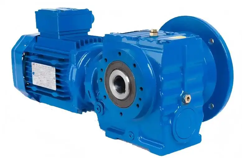
Sliding friction generates heat. It also means that a significant portion of the input power is lost to friction rather than transmitted to the output. The amount of loss depends on the ratio, the worm geometry (lead angle, number of starts), the surface finish, the lubricant, and the load.
This sliding contact mechanism has a consequence that is sometimes useful: under certain geometric conditions, the friction that resists forward motion also resists back-driving. This is the basis of worm gear self-locking, discussed in detail below.
Helical-Bevel Gear: Rolling-Dominant Contact
A helical-bevel gear set uses spiral bevel gears — gears with curved, angled teeth cut on a conical pitch surface. The teeth engage through a combination of rolling and sliding, but the rolling component dominates. The contact is more like a standard spur or helical gear mesh, just redirected through 90 degrees by the bevel geometry.
Rolling-dominant contact generates less friction, less heat, and allows higher efficiency. The trade-off is that high reduction ratios require multiple stages, which adds complexity and cost. A single-stage worm gear can achieve ratios of 60:1 or higher; achieving the same ratio with helical-bevel gears typically requires two or three stages.
Comparing worm and helical-bevel for a specific application? Send your required ratio, estimated output torque or load, and average operating hours per day. We can help assess which architecture is the better structural match based on your duty profile — before you commit to a specific model or series.
Side-by-Side Comparison
| Dimension | Worm Gear Motor | Helical-Bevel Gear Motor |
| Contact mechanism | Sliding (friction coupling) | Rolling-dominant |
| Efficiency | Lower; varies with ratio, load, lubrication, and size. Self-locking designs operate at very low efficiency | Higher; helical-bevel generally offers higher efficiency. Actual values depend on ratio, stages, and load |
| Heat generation | Higher — sliding friction converts more input power to heat | Lower — rolling contact generates less frictional heat |
| Single-stage ratio range | Wide; can achieve high ratios in a single stage | Narrower per stage; high ratios require multiple stages |
| Self-locking | Possible under certain conditions (lead angle < friction angle) | Not self-locking |
| Cost | Generally lower for equivalent ratio | Generally higher, especially at high ratios (multi-stage) |
| Noise | Low at low to moderate speeds | Low; smooth operation |
| Backlash | Can be low; adjustable in some designs | Low in precision designs; depends on manufacturing quality |
| Typical power range | Common in lower to mid-power applications; larger sizes also exist | Available across a wide power range, including high-power industrial applications |
| Maintenance | Higher operating temperature can increase lubricant thermal stress; use the oil-change interval specified for the actual gearbox and duty | Generally lower maintenance due to lower operating temperatures |
Reading this table correctly: The values shown are comparative trends, not fixed specifications. A worm gear at 10:1 ratio will have different efficiency than the same worm gear design at 60:1. A single-stage helical-bevel unit will have higher efficiency than a three-stage version. Always confirm actual efficiency, ratio, and torque ratings with the specific manufacturer’s catalog for the model you are evaluating.
Comparing worm and helical-bevel for your application? Send your required ratio, estimated output torque or load, and average operating hours per day. We can help assess which architecture is the better structural match based on your duty profile — before you commit to a specific model or series.
Self-Locking: What It Is, When It Works, and When It Does Not
Self-locking is one of the most misunderstood properties of worm gear drives. Many product descriptions mention it as a feature, but few explain the conditions and limitations clearly.
The Self-Locking Condition
A worm gear set is self-locking when it cannot be back-driven — that is, torque applied to the output (worm wheel) cannot drive the input (worm). This happens when the worm’s lead angle is smaller than the equivalent friction angle between the worm thread and the wheel tooth.
Lead angle is a geometric property of the worm — it depends on the number of thread starts and the worm diameter. Friction angle depends on the coefficient of friction between the worm and wheel materials, which in turn depends on the materials, surface finish, lubricant, temperature, and sliding speed.
This means self-locking is not a binary property of “worm gears in general.” It is a conditional outcome of specific geometric and tribological parameters. A worm gear designed with a small lead angle and appropriate materials may self-lock; a worm gear with a larger lead angle (for higher efficiency) will not.
Why Self-Locking Is Not a Safety Brake
Even when a worm gear is designed to self-lock under nominal conditions, several factors can compromise that property in service:
- Vibration: Mechanical vibration can momentarily reduce the effective friction coefficient below the threshold needed for self-locking. In a vibrating environment, a worm gear that holds when stationary may allow gradual back-driving.
- Lubricant temperature: As the lubricant warms up during operation, its viscosity decreases, and the friction coefficient changes. For example, a worm gear that self-locks at 20°C oil temperature may not self-lock at 80°C, because the lubricant viscosity and friction coefficient change with temperature.
- Wear: As the worm thread and wheel teeth wear over time, the contact geometry changes, potentially altering the self-locking condition.
- Shock loads: A sudden impact or reverse load impulse can overcome the static friction that maintains self-locking.
For these reasons, self-locking should never be relied upon as a safety holding mechanism. If a load must be held against gravity or other forces — especially where failure could cause injury or damage — use an independent, purpose-designed brake. The worm gear’s friction-based resistance may be a useful secondary characteristic, but it is not a substitute for a brake.
The Efficiency Penalty of Self-Locking
When a worm gear is designed for self-locking, it operates at very low efficiency because the same friction that prevents back-driving also resists forward motion. The energy lost to friction becomes heat, which must be managed through the gearbox housing and lubricant.
If self-locking is not required, worm gears can be designed with higher lead angles that achieve better efficiency — but these designs will not self-lock. There is a direct trade-off between self-locking capability and efficiency in worm gear design.
Choosing Based on Operating Conditions
The comparison table and self-locking discussion provide the technical background. But the practical question is: which gear type should you choose for your specific application? The answer depends on your operating profile — not on a universal ranking.
Scenario 1: Intermittent Duty, Cost-Sensitive Application
Example: A small packaging machine that runs in batches — 30 minutes on, 15 minutes off, with a total of 4–6 operating hours per day. The required ratio is 30:1. The budget is tight because the machine is a mid-range product line.
Analysis:
- The intermittent duty means the worm gear’s lower efficiency and higher heat generation are less critical — the gearbox has time to cool between cycles.
- A 30:1 ratio is well within the single-stage worm gear range, keeping the unit compact and inexpensive.
- The lower initial cost of a worm gear motor fits the budget constraint.
- If the application does not require safety holding, self-locking is not a factor either way.
Likely choice: Worm gear motor. The efficiency penalty is acceptable for intermittent duty, and the cost and simplicity advantages are meaningful.
Scenario 2: Continuous Duty, Efficiency-Priority Application
Now consider the opposite end of the duty spectrum, where the efficiency penalty of a worm gear becomes a real operating cost.
Example: A bulk material handling conveyor that runs 20 hours per day, 6 days a week. Required ratio is 20:1. The motor is 5.5 kW. The plant manager tracks energy costs closely.
Analysis:
- At 20 hours per day, the worm gear’s efficiency loss translates to wasted energy over a year. For continuous-duty equipment, compare annual input energy using the actual efficiencies and local electricity cost.
- The continuous operation means the gearbox never has a cooling break. A worm gear’s higher heat generation becomes a reliability concern — oil degrades faster, seals are stressed, and the gearbox may need more frequent maintenance.
- A 20:1 ratio is achievable in a single-stage helical-bevel design or a two-stage version, depending on the manufacturer’s range.
Likely choice: Helical-bevel gear motor. The higher efficiency reduces energy cost and operating temperature, improving long-term reliability under continuous duty.
Scenario 3: Application Where Back-Driving Is a Concern
A third factor that can override pure efficiency considerations is the risk of back-driving — when the load, rather than the motor, tries to turn the output shaft.
Example: A vertical screw conveyor that lifts material. When the motor stops, gravity tries to reverse the conveyor. The operator wants to prevent the load from back-driving the screw.
Analysis:
- A worm gear motor’s self-locking tendency may help resist back-driving under normal, non-vibrating conditions. This can reduce the duty cycle on the brake (if one is fitted) and may simplify the control system.
- However, if the material in the screw could cause injury or equipment damage if it falls back, the self-locking is not sufficient as a safety mechanism. An independent spring-applied brake is required.
- If the application runs for long periods, the worm gear’s efficiency penalty and heat generation need to be considered alongside the self-locking benefit.
Likely choice: Worm gear motor with an independent brake — the worm gear provides a secondary resistance to back-driving under normal conditions, and the brake provides the safety holding function. If the duty is continuous and efficiency is critical, a helical-bevel motor with a brake may be the better alternative, accepting that the brake will do all the holding work.
High Reduction Ratio and Compactness Trade-Off
One of the worm gear motor’s traditional advantages is the ability to achieve high reduction ratios in a single stage. A single worm gear set can provide ratios of 60:1, 80:1, or 100:1 in standard catalogs, keeping the gearbox compact.
Achieving the same ratio with a helical-bevel design typically requires two or three stages, which increases the gearbox length, weight, and cost. However, multi-stage helical-bevel units maintain higher efficiency even at high ratios, while worm gear efficiency drops as the ratio increases (more sliding, more friction, more heat).
The trade-off: compactness vs. efficiency at high ratios. If space is the primary constraint and the duty is intermittent, a worm gear motor at 60:1 may be the right choice. If the duty is continuous, the energy cost and thermal management burden of a low-efficiency worm gear at high ratio may outweigh the space savings.

What to Send a Supplier for an Initial Assessment
To get a meaningful comparison between worm and helical-bevel options for your specific application, provide:
| Parameter | Why It Matters |
| Required reduction ratio | Determines whether single-stage worm is viable or multi-stage helical-bevel is needed |
| Estimated output torque or load description | Determines gearbox size and rated torque requirement |
| Operating hours per day | Determines whether efficiency and heat are critical (continuous) or acceptable (intermittent) |
| Ambient temperature | Affects lubricant selection and thermal management |
| Start frequency (starts per hour) | Affects thermal cycling and mechanical stress |
| Space constraints (if any) | Determines whether compactness is a deciding factor |
| Back-driving concern (yes/no) | Determines whether self-locking is relevant to the decision |
| Budget range (if applicable) | Helps narrow the recommendation to a practical option |
If you are considering switching from a worm gear motor to a helical-bevel unit (or vice versa) on an existing machine, also provide the current unit’s footprint, shaft dimensions, and mounting configuration. A gear type change is not always a drop-in replacement — the mounting interface, housing dimensions, and oil level requirements may differ.
Considering a switch from worm to helical-bevel, or evaluating both for a new design? Send your operating hours, ambient temperature, and start frequency for long-running projects — these factors determine whether the efficiency advantage of helical-bevel justifies the higher initial cost. If you are replacing an existing worm unit, upload the current footprint and shaft dimensions so we can assess the physical interchangeability before you commit to a change.
Share on Social:


Contact Us
In This Article
Right Angle Geared Motor: Matching Electrical Supply, Variable Speed and Braking
Oct 26, 2026
Planning a Bevel Reducer Installation: Turn Shaft Requirements Into a Practical Drive Layout
Oct 26, 2026
Choosing an Overhead Crane Gearbox by Its Hoisting or Travel Function
Oct 26, 2026
Replacing an Industrial Worm Gearbox: What to Keep and What to Reassess
Oct 25, 2026