


 Home /
How to Check Overhung Load When a Chain Sprocket Is Moved Along a Gearbox Output Shaft
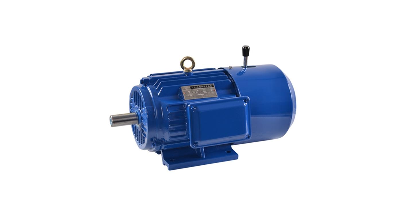
Right Angle Geared Motor: Matching Electrical Supply, Variable Speed and Braking
Oct 26, 2026
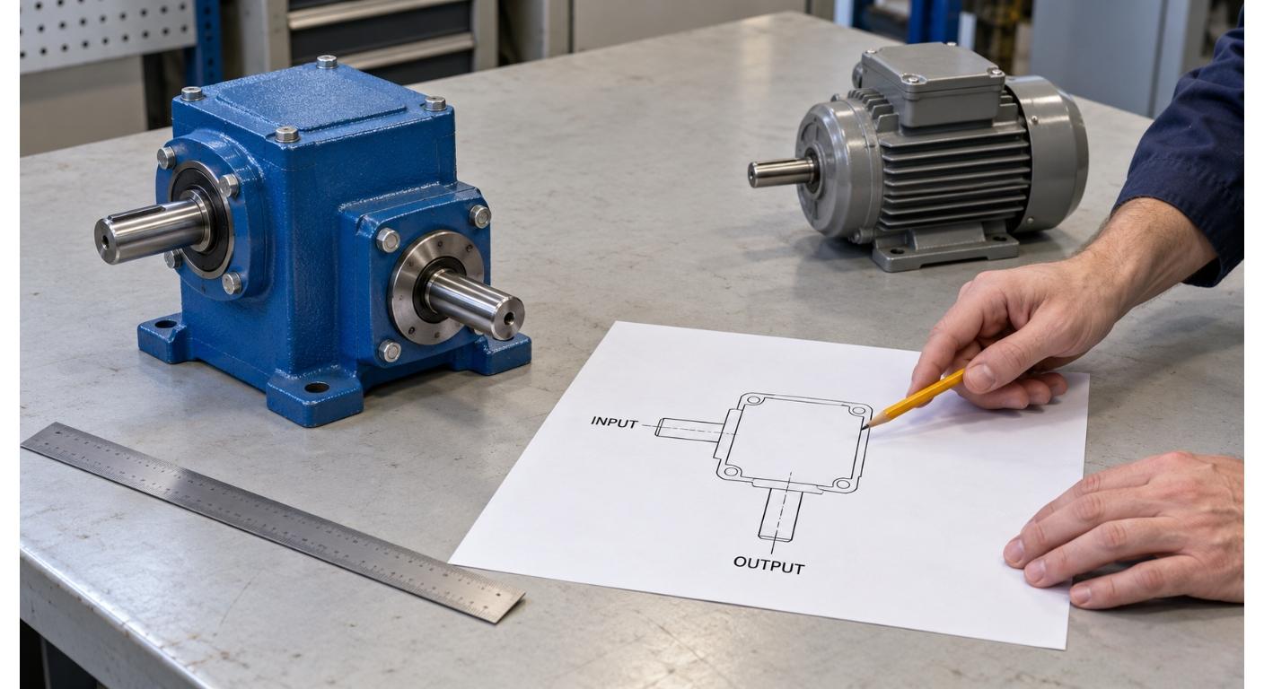
Planning a Bevel Reducer Installation: Turn Shaft Requirements Into a Practical Drive Layout
Oct 26, 2026
Choosing an Overhead Crane Gearbox by Its Hoisting or Travel Function
Oct 26, 2026
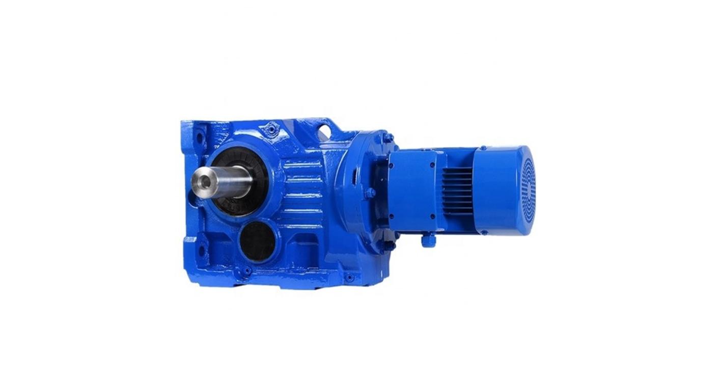
Replacing an Industrial Worm Gearbox: What to Keep and What to Reassess
Oct 25, 2026
A chain drive is reworked so the sprocket sits closer to the gearbox housing, and the assumption is that the change is safe because the sprocket is nearer the support. On paper the transmitted torque is unchanged, so nothing looks different. In practice the bearing and shaft loads can go up or down depending on which way the sprocket moved and how the chain pulls, and an unchecked layout change can leave the output bearings or shaft outside their rated load conditions.
Overhung load is the radial load applied outside the shaft's bearing support by a component such as a sprocket. Changing the sprocket position changes the lever arm, and with it the shaft bending moment and bearing reactions, even when the torque stays the same. Here is how to check it properly before the layout is committed.
Why Moving the Sprocket Changes the Bearing Load
Torque tells you how much turning effort is transmitted. It does not tell you how much radial load the bearing carries.
When a chain wraps a sprocket, the chain pulls on the sprocket in the plane of the drive. For a given radial force and shaft section, the bending moment is that force times the axial distance from the section to the sprocket's load plane. Move the sprocket farther from the bearing and the moment grows; move it closer and the moment drops, for the same load. So two drives with identical torque and identical chain tension can load the output bearing very differently, purely from where the sprocket sits along the shaft. This is why "same torque" is not a safe answer to a position change, and why the position has to be checked against the gearbox's own published load conditions.
Chain Tension Is Not the Total Radial Load
The starting point is the resultant force at the sprocket. The chain's effective pull alone is not enough to determine it, and the bearing reactions also depend on the load position and support arrangement.
The torque on the sprocket comes from the difference between the tight-side and slack-side chain tensions, acting at the pitch radius. What is often called the circumferential force, or the effective pull, is that tension difference:
F_eff = 2 × T / d
With transmitted torque T in N·m and sprocket pitch diameter d in metres, F_eff is in newtons. If d is in millimetres, use F_eff = 2000 × T / d instead. This effective pull is not the same as the total force the chain puts on the shaft. The chain has a tight side and a slack side, and their vector sum gives the chain force on the sprocket. In a common open-chain layout, the two spans pull broadly toward the other sprocket, so nearly parallel spans give a resultant close to the sum of their tensions. Other layouts require the actual vector directions; exactly opposite, collinear tension vectors would instead subtract. That is why the geometry of the chain run has to be drawn, not assumed, before the radial load is worked out. Account for tensioner effects on chain tension, component weight, and dynamic load cases. If the gearbox catalog uses a transmission-element factor to estimate the applied load from torque, use its specified method and avoid adding factors twice for the same effect.
Record the Geometry and the Support Arrangement
The radial load check starts with what is on the shaft and where. Record the following before any calculation.
Note the sprocket pitch diameter and the tooth count, since the pitch diameter sets the effective pull for a given torque. Record the axial position of the sprocket's pitch plane and its distance from the exact datum shown in the gearbox load diagram, such as a specified shaft shoulder or housing face. That catalog dimension is not automatically the distance to the nearest bearing center. Record the directions of both chain spans and the resulting pull relative to the gearbox, including whether the run is horizontal, vertical, or at an angle. Keep the sprockets aligned in their intended chain plane. Note the support arrangement, meaning which bearings carry the shaft and where they sit relative to the sprocket.
Finally, check the gearbox data for its overhung-load rating. A published overhung-load value comes with conditions: the point on the shaft where the load is assumed to act, the speed, duty and life basis, the force and rotation directions, and whether combined axial load is allowed. A rating quoted for a load at one point does not transfer to a load at another point without checking the conditions, so read the conditions before comparing. For example, SEW-EURODRIVE's off-center load guidance checks both bearing life and shaft strength and uses the lower permitted load. Its constants belong to the listed gear units, not to every gearbox.
Watch the Limits and the Rating Conditions
Two cautions keep a layout change from becoming a failure.
The first is that reducing the overhang is not automatically safe for every structure. A shorter overhang lowers the bending moment for the same load, which is generally helpful, but the actual bearing loads also depend on the support arrangement, the direction of the chain pull, and any axial component. Shaft strength, bearing reactions and the combined internal and external loads still need to remain within the permitted limits. Treat a layout change as a load-path change to be checked, not as an improvement that is guaranteed.
The second is that there is no single correction factor for overhung load. How much a position change matters depends on the gearbox, the bearing arrangement, the speed, and the duty, so a blanket factor applied across different units is not reliable. The check belongs against the specific gearbox's rating conditions, not against a rule of thumb. Separate radial and axial ratings must not be treated as a rectangular operating envelope in which both maxima can be used together. SEW-EURODRIVE's axial-force guidance, for example, separates its no-overhung-load case from combined loading, which needs a further assessment.
Before and After Checklist
| Item | Before the change | After the change | Note |
|---|---|---|---|
| Transmitted torque | Record running, starting and peak load cases | ||
| Output speed and duty | Include starts, reversals, shocks and required life | ||
| Sprocket pitch diameter | Sets effective pull for a given torque | ||
| Distance from gearbox reference point | Use the manufacturer's datum, not a convenient one | ||
| Chain pull direction | Record both span directions and the gearbox orientation | ||
| Chain tensions / catalog method | State tensioner effects and the calculation method | ||
| Support / bearing arrangement | Which bearing carries the radial load | ||
| Resultant radial load | Combine chain forces with relevant weight and other loads | ||
| Any axial component | Check whether combined load is allowed | ||
| Gearbox overhung-load rating | Note the rated acting point, speed, and life basis | ||
| Check against rating conditions | Apply the approved position correction and combined-load check | ||
| External support if needed | Engineering review before adoption | ||
| Sign-off | Recorded and owned |
If the Layout Has to Change, Review It as Engineering
When a chain run has to be reworked, the options are usually to accept the load at the new position, to add an external bearing or a load-supporting arrangement to take the radial load off the gearbox output, or to select a unit with a rating that fits the new layout. Each one needs an engineering review against the actual geometry, not a shop-floor adjustment. An external support can be designed to carry radial load and, where specified, axial load. It does not automatically remove the load from the gearbox bearings: load sharing, alignment, axial location and thermal movement must all be checked so the added support does not over-constrain the shaft. Whichever route is taken, the decision should be recorded, because the next person to move the sprocket will rely on it.
FAQ
Does moving a sprocket closer to the gearbox always reduce the load on the output bearings? Moving the load plane closer to the same bearing support lowers the bending moment from the same radial load, but it is not automatically safe for every structure. The actual bearing loads also depend on the support arrangement, the direction of the chain pull, and any axial component, so the change has to be checked against the specific gearbox's rating conditions rather than assumed to be an improvement.
Is the chain tension the same as the radial load on the shaft? No. The transmitted torque comes from the difference between the tight-side and slack-side tensions acting at the pitch radius, but the chain force on the shaft is the vector sum of both tensions in the actual span directions. The effective pull alone does not determine that force, so the chain run geometry and tension conditions have to be recorded before the resultant is worked out.
Next Step
If a chain sprocket on a gearbox output shaft is being repositioned and you want the overhung load checked rather than assumed, send us the layout drawing, the sprocket data, the distance from the gearbox reference point, and the duty. We can review the application against the relevant gearbox data and identify what must be confirmed for the proposed layout. Explore our helical gear motors, or contact us to start a configuration review.
Share on Social:


Contact Us
In This Article
Right Angle Geared Motor: Matching Electrical Supply, Variable Speed and Braking
Oct 26, 2026
Planning a Bevel Reducer Installation: Turn Shaft Requirements Into a Practical Drive Layout
Oct 26, 2026
Choosing an Overhead Crane Gearbox by Its Hoisting or Travel Function
Oct 26, 2026
Replacing an Industrial Worm Gearbox: What to Keep and What to Reassess
Oct 25, 2026