


 Home /
Parallel Shaft vs Right Angle Gearbox: Key Differences

Right Angle Geared Motor: Matching Electrical Supply, Variable Speed and Braking
Oct 26, 2026

Planning a Bevel Reducer Installation: Turn Shaft Requirements Into a Practical Drive Layout
Oct 26, 2026

Choosing an Overhead Crane Gearbox by Its Hoisting or Travel Function
Oct 26, 2026

Replacing an Industrial Worm Gearbox: What to Keep and What to Reassess
Oct 25, 2026
A parallel-shaft gearbox keeps its input and output shafts on separate, parallel axes, while a right-angle gearbox turns the drive through approximately 90 degrees. Choose parallel shaft when the machine needs an offset, compact-width transmission path; choose right angle when the motor and driven equipment must sit perpendicular, then confirm efficiency, ratio, torque, loads and duty cycle for the specific model.
Parallel Shaft Gearbox vs Right-Angle Gearbox: What Is the Difference?
A parallel-shaft gearbox uses input and output shafts whose centerlines remain parallel but offset. A right-angle gearbox places the input and output shafts at approximately 90 degrees. The correct choice depends first on the machine’s shaft path and available space, then on torque, speed, efficiency, loads and duty cycle.
| Criterion | Parallel-shaft gearbox | Right-angle gearbox | Selection implication |
|---|---|---|---|
| Shaft relationship | Separate, parallel axes | Approximately perpendicular axes | Match the gearbox to the machine’s shaft centerlines |
| Output direction | Parallel to the input direction, with an offset | Changes direction by approximately 90 degrees | Right angle can route power around an obstruction |
| Space consideration | Often suited to flat or offset layouts | Often suited to perpendicular or restricted layouts | Check width, height and axial length rather than relying on the name |
| Common gearing | Spur, helical or double-helical | Worm, bevel, hypoid or planetary may be used | Gear type affects efficiency, noise and load behavior |
| Efficiency | Depends on gearing, ratio, stages, lubrication, speed and load | Depends strongly on whether the unit uses worm, bevel, hypoid or planetary gearing | Compare model-specific data |
| Load considerations | Check radial, axial and overhung loads | Check radial, axial and overhung loads, especially at the output | Shaft arrangement alone does not determine capacity |
| Typical applications | Conveyors, material handling and offset machine drives | Perpendicular conveyor drives, mixers and compact machine modules | Begin with the required machine layout |
| Main selection risk | Assuming every parallel-shaft unit has the same envelope | Assuming every right-angle unit is a worm gearbox | Verify the drawing, gear type and operating data |
A helical geared motor combines a motor and gearbox in one drive assembly. Whether the gearbox is parallel shaft or right angle, the motor position, mounting arrangement and output-shaft design must still match the machine.
How Are the Shafts Arranged?
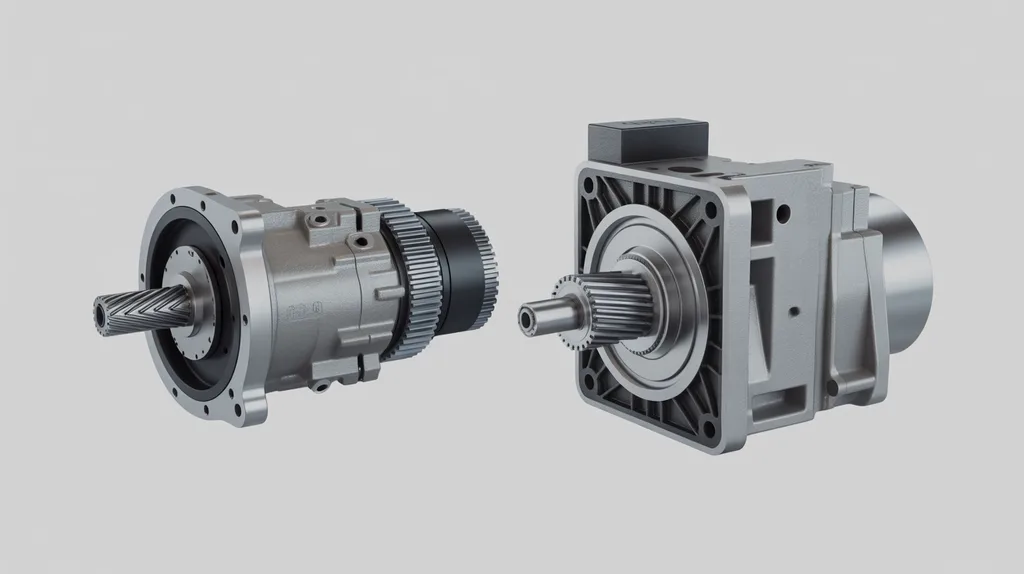
A parallel-shaft gearbox uses separate input and output shafts with parallel centerlines. A right-angle gearbox changes the direction of transmission so the input and output axes are approximately perpendicular.
The shaft arrangement determines how the gearbox fits into the machine. It does not, by itself, determine the gearbox’s efficiency, torque capacity or service life.
[DIAGRAM: Show a parallel-shaft gearbox with two offset, parallel centerlines beside a right-angle gearbox with perpendicular centerlines. Label input shaft, output shaft, shaft offset and approximately 90-degree direction change.]
Are Parallel-Shaft Gearboxes the Same as Inline Gearboxes?
No. An inline or coaxial gearbox generally has input and output shafts on the same centerline, while a parallel-shaft gearbox uses separate but parallel centerlines. Some commercial product pages use “inline” and “parallel shaft” loosely, so the manufacturer’s dimensional drawing should control the specification.
The distinction matters when space is limited. A coaxial gearbox may extend along one axis, while a parallel-shaft gearbox can place the output shaft beside the motor axis. A right-angle gearbox changes the direction of that axis instead of keeping both shafts parallel.
For a broader arrangement comparison, see inline vs right angle gearbox.
How Does Shaft Layout Affect the Machine’s Space Envelope?
A parallel-shaft gearbox is useful when the machine needs an offset drive path with parallel input and output shafts. A right-angle gearbox is useful when the motor and driven shaft must be perpendicular, when an obstruction blocks a straight drive path or when the machine frame favors a 90-degree transmission route.
Neugart notes that right-angle gearboxes are often selected for restricted space or a required input/output alignment. Bauer associates parallel-shaft gear motors with flat gearbox layouts. These are layout considerations, not guarantees that one housing will occupy less space in every installation.
Before selecting a gearbox, check:
- Are the motor and driven shaft parallel, coaxial or perpendicular?
- Is width, height or axial length the limiting dimension?
- Is an obstruction preventing a straight drive path?
- Is the output shaft solid, hollow, flange-mounted or foot-mounted?
- Does the gearbox fit inside the available frame envelope?
- Is there enough access for lubrication, inspection and removal?
- Will the motor position interfere with guards, belts, chains or other components?
A right-angle gearbox may reduce the required length in one machine but increase width or height in another. A parallel-shaft gearbox may provide a useful offset while creating a wider housing. Compare the complete gearbox-and-motor assembly against the machine drawing.
Which Gearbox Is More Efficient?
Neither shaft arrangement is automatically more efficient. Efficiency depends strongly on the gear technology, transmission ratio, number of stages, lubrication, operating speed and load.
Published figures also vary by source and product design. According to W.C. Branham, typical efficiency ranges can be approximately 50–90% for worm drives, 94–98% for helical gears and 95–99% for spiral-bevel gears. According to JIE Drive Technology, source-specific examples include more than 95% for inline helical gearboxes, approximately 85–90% for bevel gearboxes and approximately 70–80% for worm gearboxes.
Cotta reports 96–98% per stage in its parallel-shaft comparison. These figures should not be treated as universal specifications for every parallel-shaft or right-angle gearbox.
The practical comparison is therefore:
- A parallel-shaft gearbox using helical gearing may offer high transmission efficiency, but the actual result depends on the design and operating conditions.
- A right-angle gearbox using bevel gearing may have a different efficiency profile from one using worm gearing.
- A worm right-angle gearbox may trade efficiency for a particular compact layout, ratio range or operating characteristic.
- Additional stages generally affect the total transmission efficiency.
- Efficiency data should be checked for the exact model, ratio, speed, lubrication and load.
For a separate discussion of gear technology rather than shaft geometry, review helical vs worm gearbox.
What Gear Types Are Used in Parallel-Shaft and Right-Angle Gearboxes?
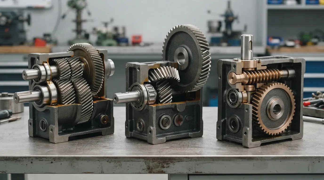
A parallel-shaft gearbox commonly uses spur, helical or double-helical gearing. A right-angle gearbox may use bevel, worm, hypoid or planetary gearing, so “right angle” describes the shaft direction rather than one specific gear design.
Neugart identifies bevel, worm, helical and planetary configurations among right-angle gearbox designs. JIE similarly describes right-angle examples using bevel, worm or planetary gearing, while parallel-shaft examples use spur or helical gears.
| Right-angle gear type | General characteristic | Efficiency consideration | What to confirm |
|---|---|---|---|
| Worm | Uses a worm and worm wheel to transmit motion at an angle | Efficiency can vary substantially with ratio, lead angle, friction and lubrication | Efficiency, thermal rating, backdriving behavior and duty cycle |
| Bevel or spiral bevel | Uses bevel gears to change the direction of transmission | Often evaluated where efficient right-angle transmission is important | Ratio, noise, torque, lubrication and shaft loads |
| Hypoid | Uses offset bevel-like gearing | Performance depends on the specific tooth geometry and lubrication | Efficiency, offset, oil requirements and load ratings |
| Planetary right angle | Combines planetary gearing with a right-angle arrangement | Must be assessed from the complete design rather than the shaft angle | Torque, speed, ratio, thermal data and mounting |
A right-angle gearbox is not automatically a worm gearbox. Similarly, a parallel-shaft gearbox is not automatically a low-speed or high-torque unit. The gear type, ratio and model rating must be verified from the manufacturer’s documentation.
What Machines Commonly Use Parallel-Shaft Gearboxes?
Parallel-shaft gearboxes are commonly considered for conveyors, material-handling systems and other machines where the input and output shafts must remain parallel but offset. Parallel-shaft gear motors are also associated with flat gearbox layouts and industrial equipment requiring a side-by-side transmission path.
Typical applications include:
- Belt and roller conveyors
- Material-handling equipment
- Packaging machinery
- Screw feeders
- Mixers with a parallel offset drive
- Plastics and rubber machinery
- Mining, cement and plant-material-handling equipment
A parallel-shaft arrangement can be a practical starting point when the machine drawing shows parallel centerlines and the available width or mounting position favors an offset gearbox. The designer must still verify output torque, radial load, duty cycle, mounting dimensions and environmental conditions.
A parallel shaft helical gearbox is the relevant product category when the input and output axes must remain parallel but offset. Mingye’s F series is the parallel-shaft helical gear-motor family identified for this application type; exact ratios, dimensions and ratings must be confirmed for the selected model.
What Machines Commonly Use Right-Angle Gearboxes?
Right-angle gearboxes are commonly selected when the motor and driven shaft must be perpendicular or when the machine layout benefits from a 90-degree change in drive direction. Right-angle bevel and worm designs can have different efficiency, load and backdriving characteristics, so application data remains essential.
Typical applications include:
- Conveyors with a perpendicular motor position
- Mixers and paddle mixers
- Packaging machinery with a turned drive path
- Material-handling equipment constrained by frame geometry
- Compact machine modules requiring a 90-degree output
- Equipment where an obstruction prevents a straight drive arrangement
A right-angle gearbox can help route power around a frame member or position the motor away from the driven shaft. However, the housing may still require substantial width, height or service clearance. Compare the complete assembly, including motor, coupling, guard and mounting hardware.
Mingye’s range includes K and S series helical gear motors. For a right-angle requirement, the exact geometry, gear type, ratio, mounting and load data should be confirmed from the applicable product documentation before specifying a model. Readers evaluating a worm-style option can review the S series helical worm gear motor information and then verify the required configuration.
Which Option Handles Torque, Speed and Shaft Loads Better?
Shaft arrangement alone does not determine torque, speed or load capacity. The selected gearbox must be checked against continuous and peak torque, input speed, transmission ratio, duty cycle, service factor, radial load, axial load, overhung load and thermal conditions.
| Selection criterion | Why it matters | Data to provide | Common mistake |
|---|---|---|---|
| Output torque | Determines whether the gearbox can drive the load | Continuous and peak torque | Selecting by motor power alone |
| Input and output speed | Affects ratio, gearing and thermal behavior | Motor speed and required output speed | Treating nominal ratio as the only speed requirement |
| Transmission ratio | Determines the reduction and output speed | Required ratio or acceptable range | Ignoring actual operating speed |
| Duty cycle | Repeated starts, stops and load changes affect sizing | Operating hours, starts per hour and load pattern | Sizing only for average running conditions |
| Radial load | Belts, chains and gears can apply side loads to the shaft | Load magnitude, direction and distance from bearing | Checking torque but not overhung load |
| Axial load | Thrust can affect bearings and shaft arrangement | Continuous and peak axial load | Assuming the gearbox absorbs any thrust |
| Mounting | Incorrect feet, flanges or shaft dimensions can prevent installation | Drawing, bolt pattern, shaft and housing dimensions | Ordering by series name only |
| Environment | Dust, moisture, heat and washdown affect the specification | Ambient temperature and contamination level | Treating all industrial environments as equivalent |
| Rotation and backdriving | The driven machine may require a particular direction or holding behavior | Rotation, stopping and backdriving requirements | Assuming a worm unit is a safety brake |
| Maintenance access | Lubrication and inspection affect practical machine uptime | Service clearances and maintenance schedule | Placing the gearbox where it cannot be serviced |
Superior Gearbox lists size, ratio, torque, mounting and environmental requirements among the factors to consider for right-angle bevel drives. Those same categories are relevant when comparing a parallel-shaft replacement.
Do not describe one arrangement as inherently stronger or more durable. A specific gearbox model, gear type, bearing arrangement, ratio and operating condition determine suitability.
How Should You Choose Between a Parallel-Shaft and Right-Angle Gearbox?
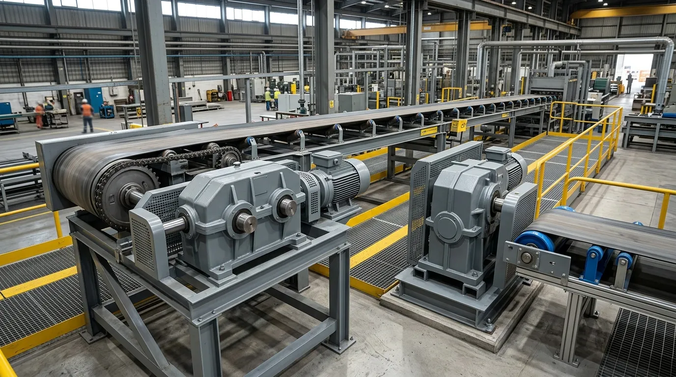
Start with the required shaft direction and available machine envelope, then compare gear technology and verify the operating loads. A parallel-shaft gearbox is the initial candidate for parallel offset shafts; a right-angle gearbox is the initial candidate for perpendicular shafts.
- Draw the shaft centerlines. Identify whether the input and output shafts are coaxial, parallel and offset, or perpendicular.
- Measure the available envelope. Record the maximum width, height and axial length, including motor and guard clearances.
- Define the output requirement. Specify output speed, required ratio, direction of rotation and any speed variation.
- Calculate continuous and peak torque. Include start-up, acceleration, shock and changing-load conditions where relevant.
- Identify shaft loads. Record radial, axial and overhung loads from belts, chains, gears, drums or other connected components.
- Select the gear technology. Compare helical, worm, bevel, hypoid or planetary designs according to efficiency, ratio, noise, thermal and load requirements.
- Confirm the mounting arrangement. Check foot or flange mounting, hollow or solid output shaft, bolt pattern, shaft dimensions and motor position.
- Review operating conditions. Confirm duty cycle, ambient temperature, contamination, lubrication and maintenance access.
- Compare model-specific data. Review the manufacturer’s efficiency, thermal, torque, speed and load information for the exact ratio and configuration.
- Check the complete assembly. Verify the gearbox, motor, coupling, guards and driven equipment against the machine drawing before ordering.
| Machine requirement | Initial direction | Reason | Verification still required |
|---|---|---|---|
| Parallel, offset shafts | Parallel shaft | Matches the required centerline arrangement | Width, output shaft, torque and radial load |
| Perpendicular shafts | Right angle | Turns power through approximately 90 degrees | Gear type, ratio, housing envelope and loads |
| Worm-based right-angle requirement | Right angle with worm gearing | Matches the specified gear technology and shaft direction | Efficiency, thermal rating and backdriving behavior |
| High-efficiency priority | Compare helical and bevel options first | Gear technology can strongly affect efficiency | Exact model data under the intended load |
| High radial-load exposure | Compare bearing and shaft-load ratings | Side loads may control gearbox selection | Load direction, distance and duty cycle |
| Tight maintenance access | Select the layout with accessible service points | Physical fit includes maintenance clearance | Lubrication, inspection and removal access |
| OEM replacement with fixed dimensions | Match the existing shaft and mounting arrangement | Compatibility may be more important than nominal series | Drawing, ratio, rotation, loads and service factor |
How Do Mingye’s F, K and S Series Fit This Comparison?
Mingye’s F series is the relevant parallel-shaft helical gear-motor family for a parallel, offset shaft arrangement. Mingye’s K and S series are product families to review when the machine requires a right-angle solution, but the exact shaft geometry, gear type, ratio, mounting and load capability must be confirmed for the selected model.
Mingye designs, makes and supplies industrial power-transmission equipment, including motors and reducers. Its own CNC-equipped factory uses modular, standardized designs, and Mingye offers OEM customization of mounting dimensions and transmission ratios.
For the parallel-shaft route, review the F series parallel shaft helical gear motor after defining the machine’s shaft centerlines and load requirements. For K or S series selection, provide the required shaft direction, ratio, torque, speed, mounting dimensions, duty cycle and environment so the applicable configuration can be checked.
Parallel Shaft or Right Angle: Final Selection Checklist
Choose the shaft arrangement that matches the machine’s centerlines first, then confirm the gearbox’s gear type, ratio, torque, loads, mounting and operating environment. A suitable replacement must match both the mechanical layout and the duty requirements.
- [ ] Input and output shaft directions measured
- [ ] Parallel, coaxial or perpendicular centerlines identified
- [ ] Available width, height and axial length recorded
- [ ] Required output speed and ratio defined
- [ ] Continuous and peak torque calculated
- [ ] Radial, axial and overhung loads confirmed
- [ ] Duty cycle and service factor identified
- [ ] Mounting and shaft dimensions matched
- [ ] Motor position and output direction checked
- [ ] Rotation and backdriving requirements reviewed
- [ ] Environment, lubrication and sealing requirements checked
- [ ] Manufacturer-specific efficiency and thermal data reviewed
- [ ] Complete gearbox-and-motor assembly checked against the machine drawing
What Is a Right-Angle Gearbox Used For?
A right-angle gearbox changes the power-transmission direction by approximately 90 degrees. It is used when the motor and driven shaft must be perpendicular, when an obstruction blocks a straight drive path or when the machine frame favors a turned transmission route. The appropriate bevel, worm, hypoid or planetary design depends on ratio, load, efficiency and duty requirements.
Are Worm Gearboxes Always Self-Locking?
No. Resistance to backdriving depends on worm geometry, lead angle, load, lubrication and operating conditions. A worm gearbox should not automatically be treated as a safety brake or guaranteed holding device. Applications requiring controlled stopping or load retention may need a separate brake or other engineered safety measure.
What Information Should I Send a Gearbox Supplier?
Provide the input power and speed, required output speed or ratio, continuous and peak torque, duty cycle, radial and axial loads, mounting dimensions, shaft configuration, rotation, ambient conditions and any OEM requirements. A machine drawing and photographs of the existing installation can also help verify physical compatibility before selection.
Share on Social:


Contact Us
In This Article
Right Angle Geared Motor: Matching Electrical Supply, Variable Speed and Braking
Oct 26, 2026
Planning a Bevel Reducer Installation: Turn Shaft Requirements Into a Practical Drive Layout
Oct 26, 2026
Choosing an Overhead Crane Gearbox by Its Hoisting or Travel Function
Oct 26, 2026
Replacing an Industrial Worm Gearbox: What to Keep and What to Reassess
Oct 25, 2026