


 Home /
What Type of Gearbox Is Best for Industrial Applications?
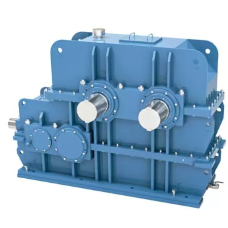
Rubber Internal Mixer Gearbox: Read the Batch Load Profile, Not Just Motor kW
Oct 22, 2026
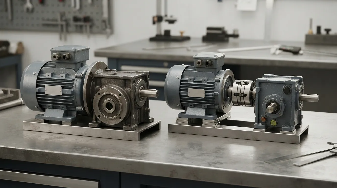
Hot Industrial Gearbox Coupling After Cold Alignment: What to Check
Oct 22, 2026
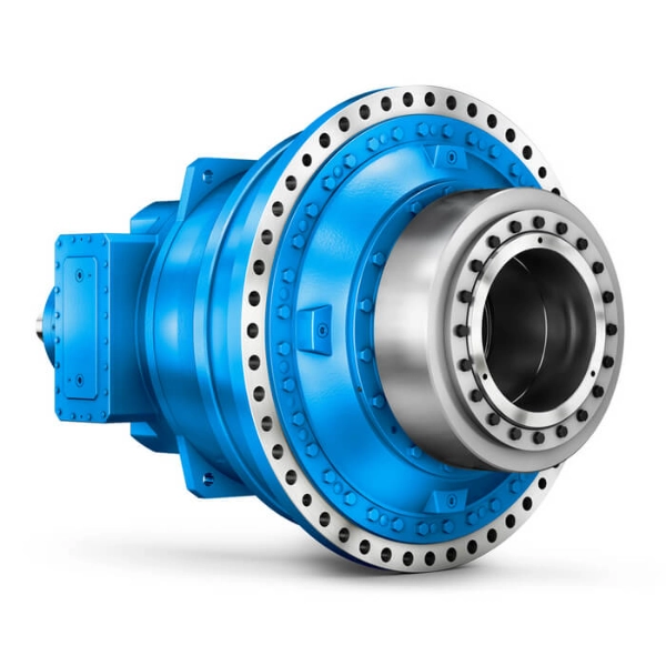
Hydraulic Slewing Drive Won't Rotate: Separate Motor, Brake and Gearbox Faults
Oct 22, 2026
Calender Roll Gap Changes: What Must the Drive Coupling Accommodate?
Oct 22, 2026
No single industrial gearbox is best for every application. Helical gearboxes suit many smooth, continuous-duty drives; worm gearboxes fit compact, high-ratio applications; planetary gearboxes deliver high torque in limited space; and cycloidal reducers are suited to demanding shock-load duties. The right choice depends on torque, speed, ratio, duty cycle, mounting, environment and required efficiency.
Which gearbox type is best for industrial applications?
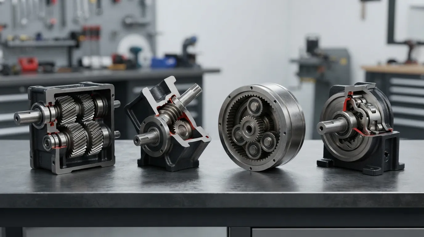
There is no universal best gearbox. Helical gearboxes are often the practical starting point for continuous-duty drives, while worm, planetary and cycloidal designs become preferable when compactness, high reduction, torque density or shock-load performance is more important.
A gearbox is a mechanical transmission that changes input speed and torque to match the driven machine. The correct selection depends on the complete operating condition, not only the motor power rating.
| Gearbox type | Best fit | Main strengths | Main limitations | Typical applications |
|---|---|---|---|---|
| Helical | Smooth, continuous-duty industrial drives | Efficient, smooth and suitable for many industrial loads | May require a different design when space, right-angle layout or severe shock loads dominate | Conveyors, mixers, packaging, plastics and rubber machinery |
| Worm | Compact, high-ratio or right-angle drives | Compact reduction and simple layout | Sliding contact can increase heat and reduce efficiency | Compact conveyors, material handling and selected right-angle drives |
| Planetary | High torque in limited space | High torque density and load sharing | More complex specification and potentially higher cost | Heavy-duty machinery, compact high-torque drives and precision-oriented systems |
| Cycloidal | Demanding duty and shock-load conditions | Robust low-speed torque transmission and suitability for demanding loads | Requires careful checking of torque, overload, speed and mounting | Mixers, material handling and heavy industrial machinery |
| Bevel or bevel-helical | Drives requiring a change in shaft direction | Transfers power between intersecting shafts | Layout and load requirements must be checked carefully | Right-angle machinery and angled drives |
| Parallel-shaft or shaft-mounted | Conveyors and material handling | Useful installation arrangement; shaft-mounted units can mount directly on the driven shaft | Shaft loads, mounting and torque-arm requirements must be confirmed | Conveyors and material-handling systems |
The table gives a starting point, not a final rating decision. Output torque, output speed, ratio, duty cycle, shock load, mounting position and environmental conditions determine whether a gearbox is suitable.
[DIAGRAM: Comparison flowchart routing continuous-duty, compact high-ratio, high-torque compact and shock-load requirements to helical, worm, planetary or cycloidal gearbox types.]
When is a helical gearbox the best choice?
A helical gearbox is usually a strong choice for smooth, efficient and reliable continuous operation. Helical gearboxes are commonly considered for conveyors, mixers, packaging equipment, plastics and rubber machinery, and other moderate-to-heavy industrial drives.
A helical gear is a gear with angled teeth. The angled teeth engage progressively and distribute load across multiple contact points, which supports smoother and quieter operation than straight-tooth gearing, according to STOBER.
According to Malloy Electric, indicative efficiency for helical gearing can range from 96% to 99% per stage. The actual result depends on the gearbox design, ratio, load, speed, lubrication and operating conditions. The range should therefore not be treated as a guaranteed rating for every helical gearbox.
Helical gearboxes are particularly suitable for:
- Conveyors and material-handling equipment
- Mixers and paddle mixers
- Packaging machinery
- Plastics and rubber machinery
- General plant equipment with regular operating cycles
- Applications requiring smooth, continuous power transmission
Gainesville Industrial Electric associates helical gearboxes with heavy-duty applications including cement, plastics and rubber machinery. However, a helical gearbox may not be the best starting point when the drive requires extremely high reduction in a compact right-angle layout, unusually high torque density or exceptional resistance to repeated impact loads.
For a detailed comparison of the two common choices, see helical vs worm gearbox.
When should you choose a worm gearbox?
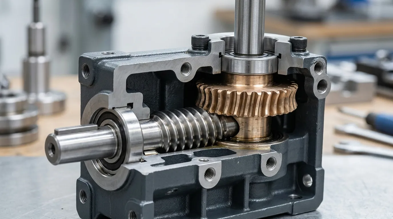
A worm gearbox is appropriate when compact, high-ratio reduction and a right-angle layout are more important than maximum efficiency. Worm gearboxes should be evaluated carefully for thermal capacity, lubrication, duty cycle and backdrivability.
A worm gearbox uses a worm screw and worm wheel to transmit motion. The arrangement can provide high reduction ratios in a compact footprint, according to STOBER.
The main trade-off is sliding contact. Sliding contact can generate more heat and reduce efficiency compared with other gearbox designs. Malloy Electric reports an indicative efficiency range of 50% to 90% for worm gearing, but the actual value depends strongly on ratio, size, lubrication, load and speed.
Worm gearboxes may suit:
- Compact conveyor systems
- Small material-handling systems
- Right-angle drives
- Applications where a compact high ratio is required
- Certain applications where reduced backdrivability is useful
Reduced backdrivability is not automatically guaranteed by every worm gearbox. The result depends on the worm geometry, ratio, lubrication, load and operating conditions. If the machine must hold a load safely, the gearbox should not be treated as a substitute for a separately specified brake or holding system unless the complete design has been verified.
Before choosing a worm gearbox, check:
- Required output speed and torque
- Reduction ratio
- Duty cycle and operating hours
- Thermal rating
- Ambient temperature
- Lubrication requirements
- Whether the output can backdrive
- Starts, stops and reversals
When is a planetary gearbox the best option?
A planetary gearbox is a strong candidate when high output torque, compact dimensions and load sharing are primary requirements. Planetary designs are useful when the available installation space is limited, but the selected unit must still be checked for torque, speed, ratio, backlash, mounting and duty cycle.
A planetary gearbox uses a central sun gear, surrounding planet gears and an outer ring gear. Multiple planet gears share the transmitted load, which helps produce high torque density and compact packaging, according to STOBER and Haydon Kerk Pittman.
Planetary gearboxes may suit:
- High-torque machinery with limited installation space
- Compact industrial drives
- Precision-oriented motion systems
- Heavy-duty equipment requiring high torque relative to size
- Applications requiring shaft, flange or foot mounting options
Amarillo Gear Service describes planetary gearboxes as suitable for applications requiring accuracy and durability and identifies shaft, flange and foot mounting as possible arrangements. These characteristics do not eliminate the need to check the specific product rating.
Malloy Electric reports indicative planetary efficiency of 96% to 99% per stage. This is a source-reported range, not a universal performance guarantee. Designers should also review backlash, radial and axial loads, lubrication, thermal behavior and the required service factor.
Planetary gearboxes can be more complex to specify than simpler reduction designs. A compact housing does not by itself confirm that the unit can handle the application’s peak torque, shock, operating hours or mounting loads.
For additional application examples, see planetary gearbox uses.
When should you choose a cycloidal reducer?
A cycloidal reducer should be evaluated when the drive faces demanding industrial duty, repeated shock loads or high low-speed torque requirements. The final choice must be based on the manufacturer’s torque, overload, speed, duty-cycle, mounting and lubrication data.
A cycloidal reducer transmits motion through cycloidal components rather than a conventional sequence of involute gear pairs. In industrial selection, cycloidal designs are commonly considered for robust, low-speed torque transmission and demanding operating conditions.
Potential applications include:
- Shock-loaded machinery
- Heavy-duty conveyors and material handling
- Mixers and industrial processing equipment
- Drives requiring high low-speed torque
- Machinery with frequent starts, stops or load changes
Malloy Electric reports an indicative efficiency range of 85% to 95% for cycloidal reducers. Efficiency depends on the particular design and operating conditions, so the range should not be used as a substitute for the manufacturer’s rating data.
Check the following before specifying a cycloidal reducer:
- Continuous and peak output torque
- Shock and overload profile
- Required output speed
- Starts, stops and reversals
- Installation space
- Mounting arrangement
- Lubrication and service access
- Ambient conditions
For a more focused application discussion, see cycloidal gearbox uses.
Which gearbox is best for conveyors, mixers and other industrial applications?
The best gearbox starting point depends on the machine’s load profile and layout. Helical, parallel-shaft and shaft-mounted reducers are common starting points for conveyors; mixers may require helical, cycloidal or heavy-duty designs; packaging often benefits from smooth, efficient gearing; and mining or cement equipment requires careful assessment of shock, duty and environment.
| Application | Likely starting point | Why it may fit | Conditions that could change the choice |
|---|---|---|---|
| Conveyors | Helical, parallel-shaft or shaft-mounted | Continuous drive operation and practical installation options | High starting torque, reversing, incline loading, space or shaft-load requirements |
| Mixers and paddle mixers | Helical, cycloidal or heavy-duty gearbox | Supports torque transmission in processing equipment | Material viscosity, starting load, shock, speed and cleaning environment |
| Packaging machinery | Helical or planetary | Smooth operation and compact high-torque options | Required precision, backlash, space and frequent cycling |
| Plastics and rubber machinery | Helical or specialized reducer | Suitable designs are available for continuous industrial processing | High temperature, process torque, duty cycle and machine-specific mounting |
| Mining and cement | Heavy-duty helical, planetary or cycloidal | Designed for demanding loads when correctly rated | Impact, dust, overload, thermal conditions and maintenance access |
| Ports and material handling | Helical, parallel-shaft, planetary or shaft-mounted | Flexible options for conveyors and lifting or handling systems | Braking, load holding, outdoor exposure, shock and shaft arrangement |
| Welding rotators | Specialized reducer, helical or cycloidal | Can be matched to controlled rotation and machine layout | Required rotational speed, positioning, load inertia and mounting |
| Small compact drives | Worm or small gear motor | Compact reduction and simple integration | Heat, efficiency, duty cycle and required output torque |
Gainesville Industrial Electric notes that shaft-mounted reducers are used for conveyors and material handling. These reducers mount directly on the driven shaft and can use an adjustable torque arm. The arrangement can simplify installation, but shaft loads, alignment and torque-arm requirements still need to be confirmed.
“Best” should therefore be read as “best matched to the machine.” A gearbox that works well on a steady conveyor may be unsuitable for a mixer with high starting torque or a mining drive exposed to repeated impact.
What specifications determine the right industrial gearbox?
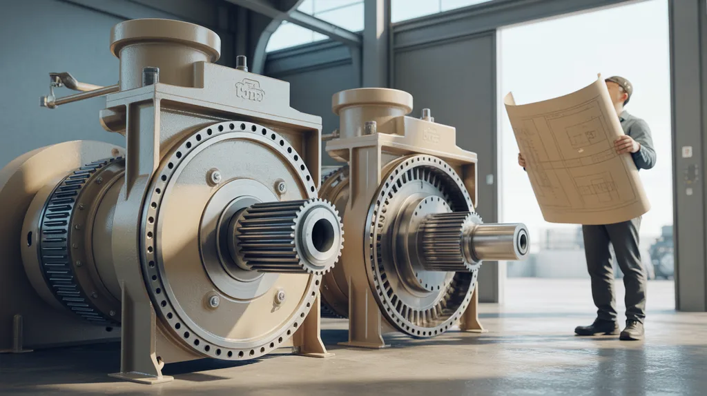
The essential gearbox selection inputs are motor power and speed, required output speed and torque, ratio, duty cycle, service factor, load profile, starts and reversals, mounting arrangement, shaft loads, environment and available space.
According to Malloy Electric, selection should account for motor characteristics, output speed and torque, load profile, starts per hour, reversals, operating hours, ambient conditions and installation environment. Gear ratio changes speed and torque, while efficiency affects usable output torque and heat.
Use this process before requesting a gearbox quotation or finalizing a design:
- Define the driven machine and operating cycle. Record what the machine does, how often it runs and whether the load is steady, variable or intermittent.
- Determine output speed and continuous torque. Use the driven machine’s actual requirements rather than selecting from motor power alone.
- Identify peak torque and shock loads. Record starting, stopping, reversing, jamming and impact conditions.
- Select the required ratio. Compare the motor speed with the required output speed.
- Check service factor and thermal requirements. The gearbox must accommodate the real duty cycle, not only the nominal running condition.
- Confirm the mounting arrangement. Review foot, flange, shaft-mounted, hollow-shaft, inline, parallel-shaft or right-angle requirements.
- Check radial and axial loads. Belt, chain, pulley and external machine loads can affect the output shaft and bearings.
- Review the environment. Consider dust, moisture, corrosion, ambient temperature, cleaning procedures and lubrication access.
- Compare efficiency and ownership factors. Consider heat, energy loss, maintenance access, downtime risk and expected operating hours.
- Validate the final selection with rating data. Obtain the manufacturer’s technical confirmation for the specific ratio, torque, speed, mounting and duty.
For a broader step-by-step selection process, see choosing an industrial gearbox.
Common gearbox-selection mistakes
- Choosing a gearbox by motor power alone.
- Ignoring peak or shock torque.
- Treating nominal torque as the only required rating.
- Overlooking starts, stops and reversals.
- Choosing a compact worm reducer without checking heat.
- Ignoring mounting position and shaft loads.
- Comparing purchase price without considering efficiency, maintenance and downtime.
- Assuming a gearbox is self-locking or non-backdrivable without confirmation.
- Selecting a ratio without verifying the required output speed.
- Forgetting the effect of ambient conditions and lubrication on operating performance.
How do efficiency, heat, shock load and maintenance affect the choice?
Efficiency affects heat generation and energy use, while shock load, backlash, duty cycle and maintenance access affect reliability and operating cost. A compact or inexpensive gearbox may be unsuitable if it runs hot, sees repeated impacts or cannot be serviced easily.
According to Malloy Electric, indicative efficiency ranges are:
- Helical gearing: 96–99% per stage
- Planetary gearing: 96–99% per stage
- Worm gearing: 50–90%
- Cycloidal reducers: 85–95%
These figures are source-reported indicative ranges, not universal ratings. Gearbox ratio, size, load, speed, lubrication, design and operating conditions can change the actual result.
| Selection factor | Helical | Worm | Planetary | Cycloidal | What to verify |
|---|---|---|---|---|---|
| Efficiency | Generally strong for continuous-duty drives | Can be lower because of sliding contact | Generally strong per stage | Depends on design and load | Product rating and operating point |
| Heat | Usually manageable when correctly rated | Important concern at high ratios or long duty cycles | Check thermal rating in compact housings | Check heat and lubrication requirements | Duty, ambient temperature and cooling |
| Compactness | Moderate, depending on configuration | Strong for compact high-ratio layouts | Strong torque-to-size ratio | Can suit demanding compact drives | Available envelope and mounting |
| Torque density | Suitable for many industrial drives | Useful but ratio and heat matter | Strong | Suitable for high low-speed torque duties | Continuous and peak torque |
| Shock-load suitability | Depends on design and service factor | Depends strongly on rating and duty | Must be checked for peak loads | Often evaluated for demanding shock-load conditions | Peak load and overload data |
| Backlash | Application-dependent | Application-dependent; backdrivability must be verified | Important in precision applications | Application-dependent | Required positioning and holding behavior |
| Maintenance | Check lubrication and seals | Lubrication and thermal management are important | Check lubrication and service access | Check lubrication and inspection requirements | Maintenance schedule and access |
| Total ownership cost | Energy and maintenance should be considered | Lower purchase cost may be offset by heat or losses | Higher complexity may be justified by compactness | Compare duty performance and service needs | Full operating cost, not price alone |
The most efficient gearbox is not automatically the best gearbox. A design with lower losses may be unsuitable if it cannot accommodate the required shock load, mounting arrangement or output torque.
How should buyers compare gearbox cost?
Industrial gearbox cost should be compared through total ownership cost rather than purchase price alone. Relevant factors include gearbox size, ratio, torque rating, mounting, efficiency, lubrication, maintenance access, duty, downtime risk and customization requirements.
A lower purchase price may not be advantageous if the gearbox creates excessive heat, requires frequent service or has insufficient capacity for the machine’s peak load. Conversely, a more complex gearbox may be justified when compact dimensions, torque density or reduced operating losses are important.
For a separate discussion of purchasing factors and quotations, see industrial gearbox price.
Final decision rule: which gearbox should you specify?
Start with a helical gearbox for many smooth, continuous-duty drives; evaluate a worm gearbox for compact, high-ratio right-angle applications; choose a planetary gearbox when high torque must fit in a small space; and consider a cycloidal reducer for demanding shock-load duties. Confirm every choice against the machine’s complete operating data.
Use this short decision rule:
- Need general continuous-duty efficiency and smooth operation? Start with a helical gearbox.
- Need compact, high-ratio, right-angle reduction? Evaluate a worm gearbox and check thermal limits.
- Need high torque in a small package? Evaluate a planetary gearbox.
- Need to manage repeated shock loads or demanding heavy-duty operation? Evaluate a cycloidal reducer or heavy-duty gearbox.
- Need a particular shaft direction or installation arrangement? Compare bevel, parallel-shaft or shaft-mounted configurations.
- Need a final specification? Validate torque, speed, ratio, service factor, duty cycle, mounting and environment with the manufacturer’s rating data.
Mingye supplies helical gear motors, heavy-duty industrial gearboxes, planetary reducers, worm gear motors and cycloidal pinwheel reducers. Mingye manufactures motors and reducers in its own CNC-equipped factory using modular, standardized designs, and offers OEM customization of mounting dimensions and transmission ratios.
OEMs and plant engineers can provide the required output speed, torque, ratio, duty cycle, mounting dimensions and application conditions to Mingye for a product-selection or customization discussion.
[DIAGRAM: Final gearbox-selection decision tree showing application requirements, gearbox type and required validation data.]
Frequently asked questions
Which type of gearbox is best overall?
No gearbox is best overall for every industrial application. Helical gearboxes suit many continuous-duty drives, worm gearboxes suit compact high-ratio applications, planetary gearboxes suit high torque in limited space, and cycloidal reducers suit demanding shock-load duties. The final decision requires torque, speed, duty cycle, mounting and environment data.
Which gearbox is best for conveyors?
Helical, parallel-shaft and shaft-mounted reducers are common starting points for conveyors and material handling. The final choice depends on conveyor speed, torque, shaft arrangement, duty cycle, starts, shock loads and installation space. Shaft-mounted reducers can mount directly on the driven shaft, but shaft loads and torque-arm requirements must be checked.
Are worm gearboxes more efficient than helical gearboxes?
Worm gearboxes are generally associated with greater sliding losses and heat than helical gearboxes, although actual efficiency depends on ratio, size, lubrication, load and speed. Malloy Electric reports indicative ranges of 50–90% for worm gearing and 96–99% per stage for helical gearing; these are not universal product ratings.
When should I choose a planetary or cycloidal gearbox?
Choose a planetary gearbox when high torque density and compact packaging are important. Evaluate a cycloidal reducer when the machine faces demanding shock-load or heavy-duty conditions. In both cases, confirm continuous and peak torque, speed, duty cycle, overload, mounting, lubrication and the manufacturer’s specific rating data.
Share on Social:


Contact Us
In This Article
Rubber Internal Mixer Gearbox: Read the Batch Load Profile, Not Just Motor kW
Oct 22, 2026
Hot Industrial Gearbox Coupling After Cold Alignment: What to Check
Oct 22, 2026
Hydraulic Slewing Drive Won't Rotate: Separate Motor, Brake and Gearbox Faults
Oct 22, 2026
Calender Roll Gap Changes: What Must the Drive Coupling Accommodate?
Oct 22, 2026