


 Home /
How to Select a Gear Motor for High Torque Applications?

Right Angle Geared Motor: Matching Electrical Supply, Variable Speed and Braking
Oct 26, 2026

Planning a Bevel Reducer Installation: Turn Shaft Requirements Into a Practical Drive Layout
Oct 26, 2026

Choosing an Overhead Crane Gearbox by Its Hoisting or Travel Function
Oct 26, 2026

Replacing an Industrial Worm Gearbox: What to Keep and What to Reassess
Oct 25, 2026
A high-torque gear motor is selected by matching the application’s continuous, starting and peak output torque—not motor power alone—while applying an appropriate service factor. Then choose the gear type, ratio and stage arrangement that meet the required speed, thermal, shock-load, mounting and environmental conditions, and confirm the complete motor-reducer combination against the manufacturer’s ratings.
What Is a High-Torque Gear Motor?
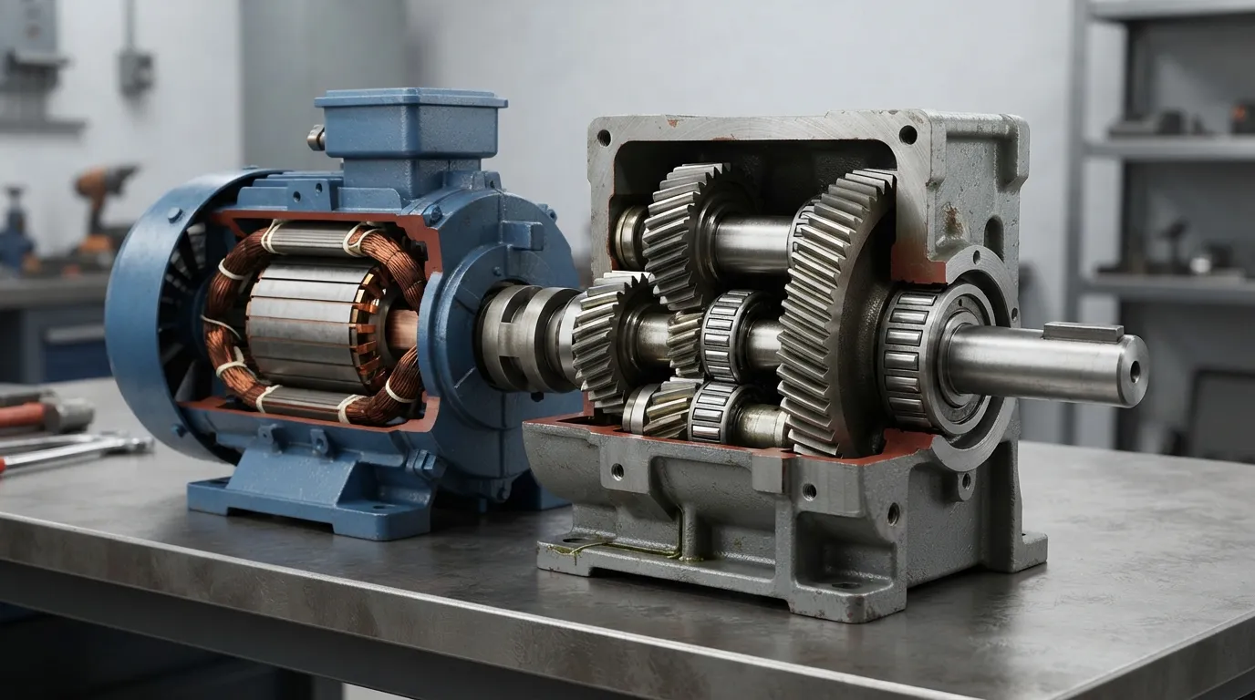
A high-torque gear motor combines an electric motor with a gear reducer to deliver lower output speed and higher output torque. The usable capacity of the complete unit depends on the application requirements and on whichever component—the motor or gearbox—has the lower applicable rating.
A gearbox reduces the motor’s rotational speed while multiplying torque at the output shaft. However, a larger motor does not automatically make every gearbox suitable for a high-torque application. The motor, gear train, bearings, shafts, housing, lubrication and thermal conditions must all support the required load.
For selection purposes, “high torque” should not be treated as one universal numerical category. A torque level that is high for a small positioning mechanism may be modest for a conveyor, mixer or mining drive. The correct question is whether the complete gear motor can safely deliver the required torque at the required speed, duty cycle and load profile.
| Selection limit | What to check |
|---|---|
| Motor-related limit | Power, speed, starting capability and thermal loading |
| Gearbox-related limit | Continuous output torque, peak torque, shaft loads, heat and service life |
| Application-related limit | Load inertia, shock, starts, stops, reversals and operating environment |
What Information Do You Need Before Selecting a High-Torque Gear Motor?
Start with the driven load, output speed, continuous and peak torque, starting conditions, duty cycle and operating environment. Mounting, shaft loads, available space, power supply and control details are also required because torque alone does not determine a suitable gear motor.
Prepare the following information before comparing product families:
- Driven load, mass, inertia or resistance
- Required output speed and allowable speed variation
- Continuous, starting, peak and stall torque
- Starts per hour, reversals and acceleration time
- Shock loads, impacts, jams or sudden stops
- Output-shaft radial and axial loads
- Mounting position and shaft orientation
- Available installation space
- Ambient temperature, dust, moisture and washdown conditions
- Lubrication and maintenance requirements
- Motor voltage, frequency, phase and control method
- Brake or load-holding requirements
- Required transmission ratio
- Output shaft arrangement and mounting dimensions
According to Bodine Electric, output torque, start/stop frequency, shock loads, operating speed, actual load and operating temperature can all affect gearhead life. STOBER likewise identifies torque, speed, physical layout, environment, alignment, duty cycle and peak loads as selection considerations.
A complete application description is especially important for conveyors, mixers, plastics and rubber machinery, packaging equipment, mining equipment and other machines that may start under load or experience changing resistance.
How Do You Calculate the Required Torque and Gear Ratio?
Calculate the required output torque from the driven load, determine the target ratio from motor speed and output speed, then account for efficiency and service factor. The final selection must be checked against both continuous and peak gearbox ratings.
Use the following preliminary process:
- Define the driven-load requirement. Determine the torque needed at the machine’s output shaft during normal operation.
- Record the required output speed. Include the acceptable operating range, not only the nominal speed.
- Estimate the ratio.
Required ratio ≈ motor speed ÷ desired output speed
- Relate torque, speed and power. Output power depends on torque and rotational speed. Transmission efficiency must be considered when relating motor power to available output torque.
- Apply an appropriate service factor. Account for shock, starts, stops, reversals, load variation and uncertainty in the application data.
- Check continuous torque. Confirm that the gearbox can carry the normal load without exceeding its continuous rating or thermal capability.
- Check starting and peak torque. Confirm that the motor can accelerate the load and that the gearbox can withstand short-duration peaks.
- Verify the complete assembly. Review the applicable manufacturer’s ratings, performance curves, thermal limits and installation conditions.
For a more detailed calculation sequence, review the gear motor torque speed calculation guide. If the application uses a separate industrial gearbox, the industrial gearbox torque sizing guidance can help organize the sizing data.
According to Haydon Kerk Pittman, output power should be calculated from torque and speed, followed by checks of ratio, efficiency and continuous torque. That sequence is useful as a preliminary method, but it does not replace verification against the selected gearbox’s technical documentation.
[DIAGRAM: Show the selection path from load torque and output speed to ratio, service factor, gear type and final motor-reducer verification.]
What Is the Difference Between Continuous, Starting, Peak and Stall Torque?
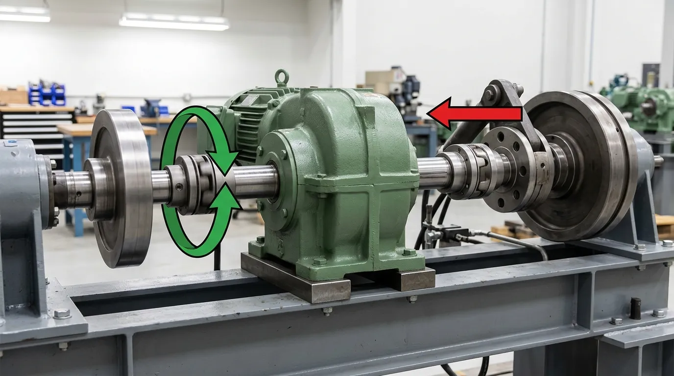
Continuous torque is the torque required during normal operation. Starting torque accelerates the load, peak torque covers a short-duration high-load event, and stall torque describes a motor condition in which speed falls to zero. These values must be evaluated separately.
| Torque term | When it applies | Selection question |
|---|---|---|
| Continuous torque | Normal running | Can the gearbox carry the load and manage heat continuously? |
| Starting torque | Acceleration or loaded start | Can the motor and reducer start the load without overload? |
| Peak torque | Short-duration high-load event | Can the gearbox withstand the event without damage? |
| Stall torque | Motor at zero speed | Is the condition permitted, controlled or protected? |
Motor stall torque and gearbox peak capacity are not interchangeable. A motor may produce a high torque during a brief stall condition, but that does not mean the gearbox, shaft or coupling can accept the same value safely.
A loaded mixer, conveyor or rotator may require substantially more torque during acceleration than during steady running. That starting requirement should be identified separately rather than hidden inside an average torque value.
Haydon Kerk Pittman’s worked example also shows why instantaneous torque can remain the governing gearbox requirement even when a reduced duty cycle lowers the calculated root-mean-square torque. A lower average demand does not automatically eliminate the need to check the highest short-duration load.
How Should Service Factor and Duty Cycle Affect Selection?
Service factor provides design margin above the calculated application requirement, but the appropriate margin depends on the actual duty. Shock loads, frequent starts, reversals, high inertia, uncertain load data and harsh operating conditions generally require more careful allowance than a smooth, steady load.
A service factor should not be selected as an arbitrary universal number. Confirm how the relevant manufacturer defines and applies it, and determine whether the value relates to the motor, gearbox or complete gear motor.
Use these decision rules:
- Treat a loaded start as a separate check from steady-state running.
- Increase the required margin when the load includes impacts, jams or reversals.
- Consider starts per hour and acceleration time, not only running hours.
- Check thermal performance for continuous operation.
- Use actual load data whenever possible instead of compensating for uncertainty with an unexplained oversized unit.
- Confirm both continuous and peak gearbox ratings.
- Do not assume that intermittent operation makes every peak load acceptable.
According to Bodine Electric, continuous-duty applications should use a gear motor with a torque rating higher than the expected application torque. The same source identifies start/stop frequency, shock loads, speed and operating temperature as factors affecting gearhead life.
Which Gear Motor Type Is Best for High Torque?
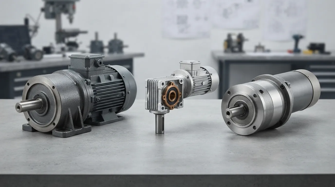
No gear type is best for every high-torque application. Helical and parallel-shaft designs suit many continuous industrial drives, worm units can provide compact right-angle transmission, and planetary reducers can be considered where high torque relative to package size is important.
The correct choice depends on output torque, speed, ratio, stage arrangement, efficiency, heat, shock loading, physical layout and maintenance requirements.
| Gear type or Mingye example | Typical reason to consider it | Main checks before selection |
|---|---|---|
| Helical gear motor — R, S, K or F series example | Continuous industrial transmission and progressive tooth engagement | Output torque, speed, mounting, shaft loads, duty and environment |
| Parallel-shaft helical — F series example | A parallel-shaft layout where machine geometry and space are important | Mounting dimensions, output shaft loads, ratio and available space |
| Helical-worm or worm — NMRV range example | Compact right-angle transmission and layout flexibility | Heat, efficiency, duty, back-driving, lubrication and load profile |
| Planetary reducer — heavy-duty planetary example | High torque relative to package size | Peak torque, ratio, thermal limits, backlash and duty cycle |
| Heavy-duty industrial gearbox — HB range example | Demanding industrial transmission applications | Continuous and peak torque, shock loads, thermal performance and mounting |
Helical and Parallel-Shaft Gear Motors
Helical gears engage progressively and distribute load across the tooth surface. This supports smooth torque transfer and makes helical arrangements relevant to many industrial drives.
Mingye’s range includes R, S, K and F series helical gear motors. These names identify available product families, not a preselected solution for every load. The final choice still requires the application torque, speed, ratio, mounting and operating data.
A parallel-shaft configuration can be useful when the driven machine requires a particular shaft arrangement or a compact installation in the available space. Review the F series parallel shaft helical gear motor 1.html page when assessing that type of layout.
Helical-Worm and Worm Gear Motors
Worm gearing can provide a compact right-angle arrangement and may be suitable where layout and packaging are important. However, worm gearing is generally less efficient and produces more heat than parallel-shaft or planetary arrangements, according to Bodine Electric.
That trade-off makes thermal checking important, particularly during continuous operation. Check operating temperature, duty cycle, lubrication, efficiency requirements and the possibility of back-driving before selecting a worm arrangement.
Do not treat a worm gear motor as automatically self-locking or fail-safe. Any holding or safety function must be evaluated against the actual mechanism and required safety controls.
Planetary Reducers
Planetary gear arrangements distribute load through multiple planet gears and can provide high torque relative to package size. They may be considered where compact packaging, torque density or a particular ratio arrangement is important.
Planetary selection still requires checks of peak torque, continuous torque, thermal performance, backlash, shaft loads and duty cycle. The presence of multiple planet gears does not remove the need to verify the complete reducer against the application.
Heavy-Duty Industrial Gearboxes
A heavy-duty industrial gearbox may be appropriate for larger or more demanding transmission duties, depending on the required torque, speed, layout and operating conditions. Mingye supplies HB series heavy-duty industrial gearboxes and heavy-duty planetary reducers as part of its industrial power-transmission range.
Exact capacity, ratio, efficiency and thermal performance must be confirmed from the applicable technical documentation. Product-family names alone are not sufficient to select a gearbox.
What Mechanical and Environmental Checks Are Required?
Confirm mounting position, shaft orientation, radial and axial loads, alignment, lubrication, ambient temperature, dust, moisture and available cooling. A gear motor with adequate nominal torque can still be unsuitable if shaft loads, heat or installation conditions exceed its permitted limits.
Check the following before final selection:
- Mounting and geometry: Confirm foot, flange, shaft and housing dimensions.
- Radial and axial loads: Check loads from belts, chains, couplings, conveyors or other driven components.
- Alignment: Ensure the motor-reducer and driven machine are aligned according to the applicable installation requirements.
- Lubrication: Confirm lubricant type, quantity, maintenance access and operating orientation.
- Temperature: Check ambient temperature and the ability to dissipate heat.
- Environment: Account for dust, moisture, washdown, corrosive exposure and other contaminants.
- Back-driving and holding: Determine whether the load can drive the output shaft when the motor is stopped.
- Controls: Confirm compatibility with the intended motor starter or variable-frequency-drive arrangement.
- Maintenance: Consider inspection access, replacement requirements and the consequences of downtime.
STOBER identifies physical layout, environment and alignment as selection factors. Bodine Electric also includes mounting, temperature and duty-cycle considerations in gearmotor application guidance.
What Mistakes Should You Avoid When Selecting a High-Torque Gear Motor?
The most common mistakes are selecting by motor power alone, using continuous torque to represent a loaded start, ignoring peak or shock loads, overlooking shaft loads and choosing a gear type without checking heat, efficiency and layout.
Avoid these errors:
- Selecting by motor power alone. Motor power does not confirm the required output torque, ratio or gearbox capacity.
- Checking only continuous torque. Starting and peak torque may govern the selection.
- Using an arbitrary service factor. The margin should reflect the actual duty, shock and uncertainty.
- Ignoring inertia and acceleration. A load may require much more torque during startup than during steady running.
- Overlooking reversals and starts per hour. Frequent cycling affects mechanical and thermal loading.
- Failing to identify the limiting component. The motor and gearbox may have different torque limits.
- Ignoring output-shaft loads. Belt, chain and other arrangements can impose radial or axial loads that are separate from transmitted torque.
- Choosing a worm unit without checking heat. Compact packaging does not remove efficiency and thermal considerations.
- Treating stall torque as allowable gearbox torque. A motor’s stall condition is not automatically a safe reducer operating condition.
- Omitting mounting and environmental data. A technically adequate torque rating cannot compensate for an unsuitable installation.
- Skipping performance-curve checks. Selection should be validated against the manufacturer’s curves and technical information.
Groschopp’s selection guidance emphasizes reviewing performance curves and testing rather than relying only on a nominal product description.
What Information Should You Send to a Gear Motor Manufacturer?
Send the manufacturer the required output torque and speed, torque profile, duty cycle, starting conditions, shaft loads, mounting arrangement, environment, motor supply and space limits. Complete data allows the motor, reducer, ratio and customization requirements to be evaluated together.
Include:
- Application and driven-machine description
- Continuous, starting and peak torque
- Output speed and required transmission ratio
- Motor voltage, frequency, phase and control method
- Starts per hour, reversals and acceleration time
- Load inertia, shock or jam conditions
- Radial and axial shaft loads
- Mounting dimensions, shaft arrangement and orientation
- Ambient temperature, dust, moisture and washdown conditions
- Brake, back-driving or holding requirements
- Space, noise and maintenance constraints
- Required timing and OEM mounting-dimension requirements
Mingye designs, makes and supplies industrial power-transmission equipment, including motors and reducers. Its range includes helical gear motors, heavy-duty industrial gearboxes, planetary reducers, worm gear motors, cycloidal reducers, cylindrical gear reducers and three-phase asynchronous motors.
Mingye manufactures motors and reducers in its own CNC-equipped factory on modular, standardized designs. It also offers OEM customization of mounting dimensions and transmission ratios and normally delivers in 7–15 days. These are company capabilities and normal delivery information; suitability, final specifications and delivery for a particular application require confirmation.
For the broader OEM procurement process, review the gear reduction motor buying guide.
A Practical High-Torque Gear Motor Selection Sequence
The selection sequence is: define the load, calculate continuous and peak torque, determine output speed and ratio, apply an application-appropriate service factor, select the gear arrangement, verify thermal and shaft-load limits, and confirm the complete motor-reducer combination.
- Define the driven load and operating profile.
- Determine the required output speed and approximate ratio.
- Separate continuous, starting, peak and stall torque.
- Apply a service factor based on shock, duty cycle, starts and load uncertainty.
- Shortlist helical, parallel-shaft, helical-worm, planetary or heavy-duty configurations.
- Check motor power, starting capability and gearbox torque.
- Verify thermal, mounting, radial-load, axial-load and environmental limits.
- Confirm the selection using the applicable manufacturer documentation.
- Send the complete application data to the manufacturer before finalizing the order.
For early sizing context, clarify what size gear motor the load, speed and output requirements call for before comparing specific gearbox arrangements.
Share on Social:


Contact Us
In This Article
Right Angle Geared Motor: Matching Electrical Supply, Variable Speed and Braking
Oct 26, 2026
Planning a Bevel Reducer Installation: Turn Shaft Requirements Into a Practical Drive Layout
Oct 26, 2026
Choosing an Overhead Crane Gearbox by Its Hoisting or Travel Function
Oct 26, 2026
Replacing an Industrial Worm Gearbox: What to Keep and What to Reassess
Oct 25, 2026