


 Home /
What Is the Gear Ratio of a Cycloidal Reducer?
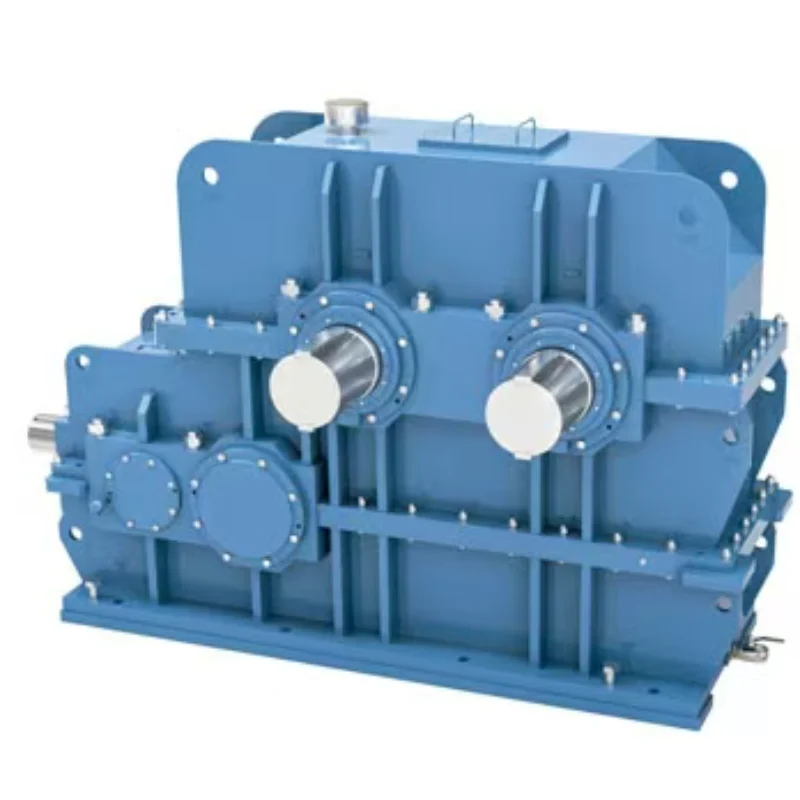
Rubber Internal Mixer Gearbox: Read the Batch Load Profile, Not Just Motor kW
Oct 22, 2026
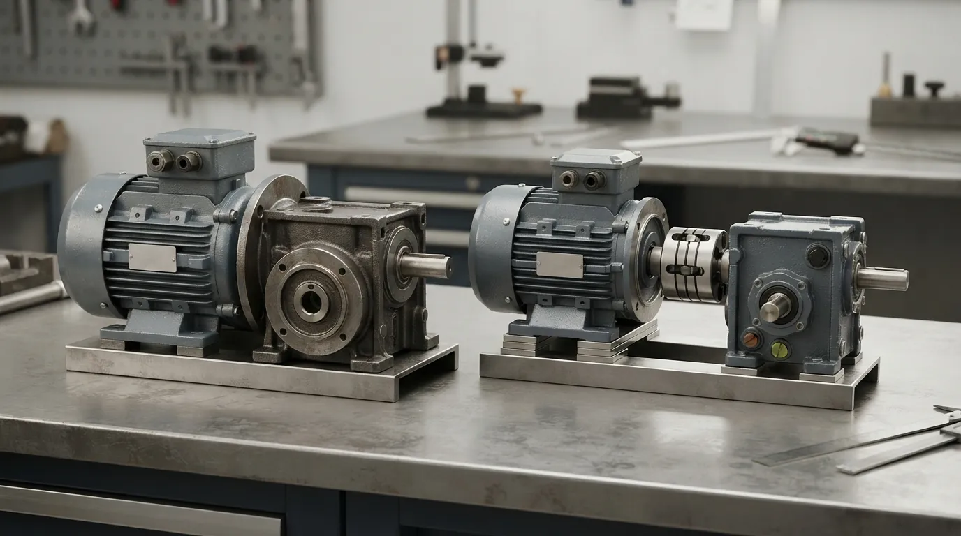
Hot Industrial Gearbox Coupling After Cold Alignment: What to Check
Oct 22, 2026
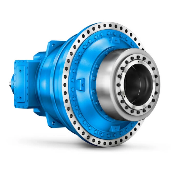
Hydraulic Slewing Drive Won't Rotate: Separate Motor, Brake and Gearbox Faults
Oct 22, 2026
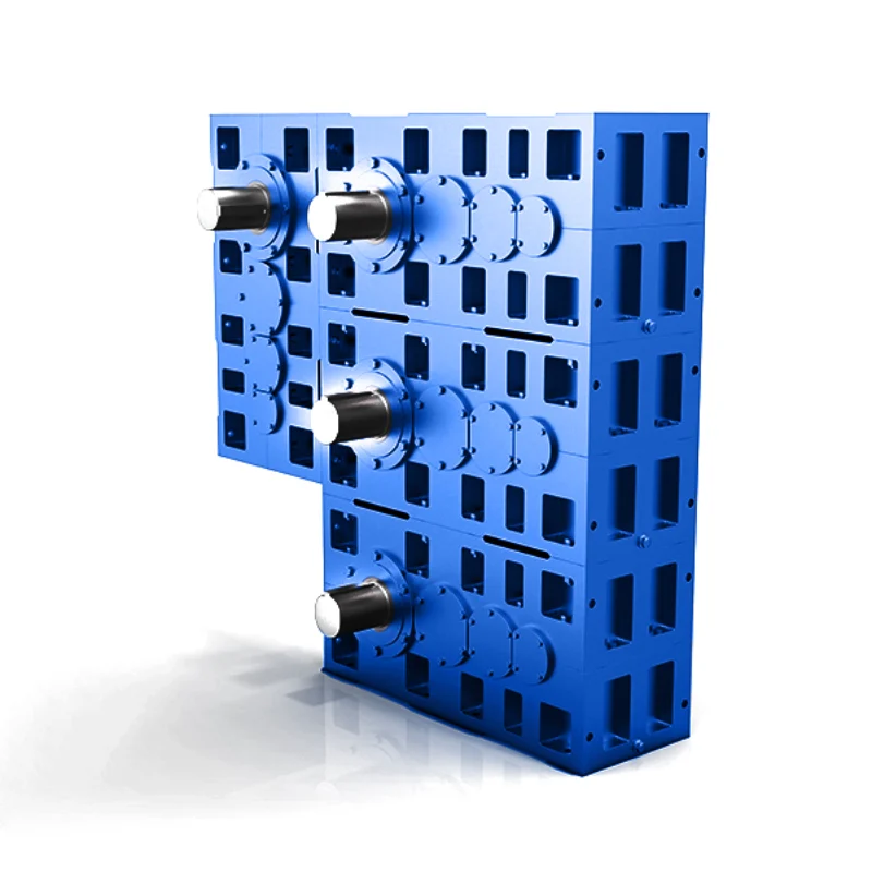
Calender Roll Gap Changes: What Must the Drive Coupling Accommodate?
Oct 22, 2026
A cycloidal reducer's gear ratio is determined by the number of pins (P) in the fixed ring and the number of lobes (L) on the cycloidal disc, calculated as (P−L)/L. With the common one-lobe difference, a 10-pin ring and 9-lobe disc gives a 9:1 reduction. Single-stage units typically range from about 5:1 to 119:1, and double-stage designs reach far higher.
What Is a Cycloidal Reducer?
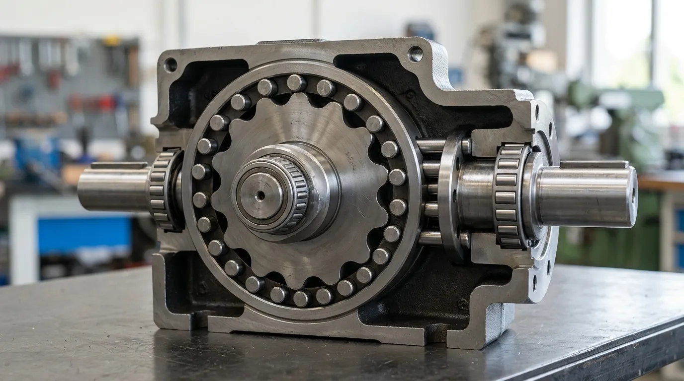
A cycloidal reducer is a type of gearbox that transmits power through an eccentric cam that drives one or two lobed discs against fixed ring pins. Unlike conventional gears that mesh tooth-to-tooth, the cycloidal disc rolls internally around the pins, producing high reduction ratios in a compact package with very low backlash.
According to Nabtesco, a cycloidal reducer has four core components: the cycloidal disc, the ring pins, the eccentric shaft (or cam), and the output mechanism. The disc is driven eccentrically so that it orbits inside the ring of pins, and this orbital motion is converted into slow, concentrated rotation at the output shaft.
One of the key advantages of this design is load distribution. According to FIRGELLI, at any moment 60–70% of the lobes share the load simultaneously, which is why cycloidal reducers handle shock loads well. Many designs also mount two cycloidal discs 180° apart to balance vibration, as explained by tec-science.
What Exactly Is the Gear Ratio of a Cycloidal Reducer?
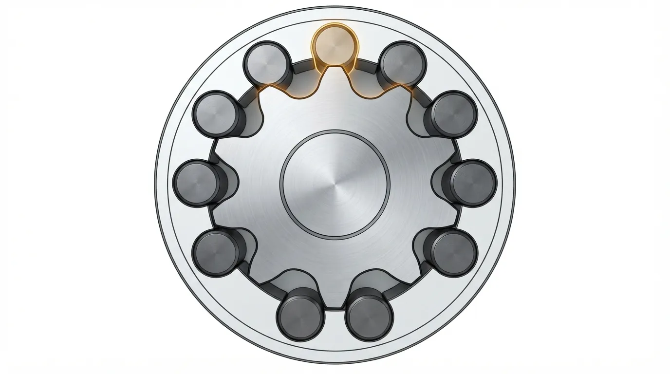
The gear ratio of a cycloidal reducer is the relationship between the number of fixed ring pins (P) and the number of lobes (L) on the cycloidal disc, calculated using the formula (P−L)/L.
In most designs, the lobed disc has exactly one fewer lobe than the ring has pins. This one-lobe difference means the disc advances by one pin position per input revolution, and the ratio equals the number of lobes on the disc.
Different manufacturers and technical sources write the formula with different variable names, which can be confusing when comparing documents. The table below reconciles the three most common notations:
| Notation | Formula | Variable meaning | Example source |
|---|---|---|---|
| r = (P−L)/L | r = ratio, P = ring pins, L = disc lobes | Wikipedia | |
| R = L/(P−L) | R = ratio, L = lobes, P = pins | FIRGELLI | |
| i = n/(N−n) | i = ratio, n = lobes, N = ring pins | tec-science |
All three formulas are mathematically identical. The result represents how many input revolutions are needed to produce one output revolution. A ratio of 9:1 means the input shaft rotates nine times for every single rotation of the output shaft.
Commercial cycloidal reducers commonly offer ratios from 30:1 to over 300:1, according to Nabtesco, with catalog standards at 1:50, 1:80, 1:100, and 1:120 as listed on DirectIndustry manufacturer listings.
How Do You Calculate the Ratio?
To calculate the gear ratio, count the ring pins and the disc lobes, then apply the formula (P−L)/L.
Worked example: With 10 pins (P=10) and 9 lobes (L=9), the calculation is (10−9)/9 = 1/9. This means the disc rotates once for every 9 input revolutions — a 9:1 reduction, as demonstrated by tec-science.
How to Calculate the Ratio in 3 Steps
- Count the number of fixed ring pins (P). These are the cylindrical pins mounted in the outer housing.
- Count the number of lobes (L) on the cycloidal disc. The lobes are the rounded projections around the disc's circumference.
- Apply the formula (P−L)/L. The result is the reduction ratio. In some notations the result is negative, which simply means the output reverses direction relative to the input.
The one-lobe difference is standard in most industrial reducers, but multi-lobe configurations exist. For example, tec-science shows that a 10-pin ring with a 7-lobe disc produces a 7:3 ratio, which equals only 2.33:1. The table below shows several configurations:
| Ring pins (P) | Disc lobes (L) | Lobe difference | Ratio | Configuration |
|---|---|---|---|---|
| 6 | 5 | 1 | 5:1 | One-lobe |
| 10 | 9 | 1 | 9:1 | One-lobe |
| 12 | 11 | 1 | 11:1 | One-lobe |
| 10 | 7 | 3 | 7:3 | Multi-lobe |
| 119 | 118 | 1 | 118:1 | One-lobe (max typical) |
Why Is the Output Rotation Reversed?
The output of a cycloidal reducer rotates in the opposite direction to the input because the disc rolls internally around the fixed pins rather than meshing externally like conventional gears.
According to Wikipedia, the output direction is opposite to the input — a property called retrograde rotation. This happens because the cycloidal disc's center moves eccentrically while the disc itself orbits within the ring of pins. The disc does not rotate on its own axis; instead, its orbital motion is converted to slow rotation at the output through the output pins or rollers.
This is why some formula notations show a negative ratio. ZHY Gear presents a worked example with 12 pins and 11 lobes, giving a ratio of i = −12. The negative sign simply indicates the reverse direction — it does not affect the magnitude of the reduction.
When planning your application, account for this direction reversal. If your machinery requires the output to rotate in the same direction as the input, you will need an additional gear stage or a different reducer type (such as a planetary gearbox, which does not reverse direction).
What Ratios Are Achievable in a Single Stage?
Single-stage cycloidal reducers typically deliver from about 5:1 to 119:1, with most commercial catalog units falling in the 30:1 to 120:1 range.
According to Wikipedia (citing Sumitomo's Cyclo 6000 series), single-stage reductions are commercially available up to 119:1. Nabtesco confirms that high reduction ratios from 30:1 to over 300:1 are achievable in a single stage. DirectIndustry manufacturer listings show ratio ranges from 41:1 to 164:1, with common catalog ratios at 1:50, 1:80, 1:100, and 1:120.
The practical upper limit for a single stage is set by the maximum practical number of pins and lobes that can be machined into the ring and disc. Beyond roughly 119:1, the components become impractically large or difficult to manufacture with the required precision.
At the lower end, ratios below 10:1 are possible but uncommon in industrial applications, because other reducer types (such as planetary gearboxes) are more efficient and cost-effective at those ratios. The multi-lobe example above (7:3 ratio) shows how reducing the lobe difference below one produces much lower ratios.
How Far Can Double-Stage Cycloidal Reducers Go?
Double-stage cycloidal reducers multiply two single-stage ratios together, reaching up to 7,569:1 while maintaining a compact footprint — at the cost of lower efficiency.
According to Wikipedia, double-stage cycloidal reducers are commercially available up to 7,569:1 (for example, a 119:1 first stage combined with a 63:1 second stage). Total ratios up to 13,600:1 have been documented in DirectIndustry manufacturer listings.
The trade-off is efficiency. Wikipedia, citing Prof. J. Darali's analysis, reports that single-stage cycloidal reducers approach 93% efficiency, while double-stage units drop to approximately 86%. Each additional stage adds friction and power loss.
For extremely high ratios, a cycloidal reducer is often a better choice than stacking multiple planetary stages, because a double-stage cycloidal unit achieves ratios that would require three or more planetary stages — with less complexity and fewer components to maintain.
That said, if your application requires ratios below 30:1, a single-stage planetary gearbox is usually more efficient and more cost-effective than a cycloidal unit.
How Does Cycloidal Ratio Compare to Planetary Gearboxes?
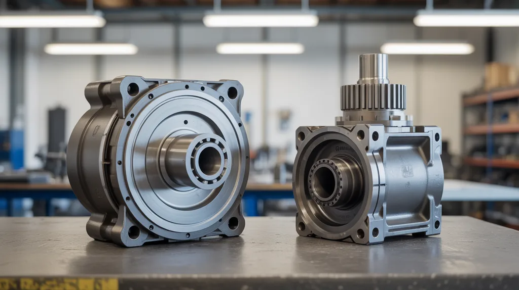
Cycloidal reducers achieve higher single-stage ratios (up to 119:1) than typical planetary gearboxes (usually 3:1 to 100:1 per stage), with lower backlash and better shock tolerance — but planetary units are often more efficient at lower ratios.
According to FIRGELLI, cycloidal reducers handle shock loads up to 500% of rated torque without tooth breakage — a major advantage in applications with variable or impact loading. The load-sharing characteristic (60–70% of lobes engaged at any moment) is the reason for this robustness.
Planetary gearboxes, by contrast, typically offer higher efficiency at lower ratios (95–97% per stage) and do not reverse the output direction. They are often preferred where efficiency is critical and the required ratio is below 50:1.
Cycloidal reducers also excel in compactness at high ratios. A ResearchGate study on cycloidal gearbox design demonstrated a 20:1 reduction achieved in a 60×60×20mm space, with torque increasing from 0.45 Nm to 8.82 Nm — a nearly 20-fold torque multiplication in a very small package.
With regard to backdriving: cycloidal reducers can be backdriven under certain conditions, but the high friction and the geometry of the rolling elements make them significantly harder to backdrive than planetary gearboxes of the same ratio.
Which Ratio Do You Need?
Choose the ratio based on the required output speed and torque: robotics and indexing applications need high ratios (50:1 to 100:1+) with low backlash, while conveyors and mixers can use moderate ratios (10:1 to 30:1) where shock-load tolerance matters more.
The table below maps common industrial applications to typical ratio ranges:
| Application | Typical ratio range | Key requirement |
|---|---|---|
| Robotics / indexing tables | 50:1 – 100:1+ | Low backlash, high precision |
| Conveyors / material handling | 10:1 – 30:1 | Shock-load tolerance, reliability |
| Mixers / agitators | 20:1 – 60:1 | High torque at low speed |
| Packaging machinery | 30:1 – 80:1 | Compact size, smooth operation |
| Welding rotators | 40:1 – 120:1 | High torque, low speed |
For a fuller list of where these ratios matter in practice, see our guide to cycloidal gearbox applications.
When the application demands both high ratio and high torque in a compact package, the combination is what makes cycloidal gearbox high torque performance attractive compared to multi-stage planetary alternatives.
If you are still deciding between reducer types, our gearbox ratio selection guide walks through the decision step by step. For a complete comparison of decision criteria beyond ratio alone, see how to choose cycloidal reducer.
Mingye designs and supplies cycloidal pinwheel reducers as part of its range of industrial power transmission equipment, built in its own CNC-equipped factory on modular, standardized designs. The company offers OEM customization of mounting dimensions and transmission ratios, and typically delivers in 7–15 days. Mingye serves OEMs and plant engineers across plastics and rubber, mixing, conveying, packaging, mining, cement, power, and port industries.
Share on Social:


Contact Us
In This Article
Rubber Internal Mixer Gearbox: Read the Batch Load Profile, Not Just Motor kW
Oct 22, 2026
Hot Industrial Gearbox Coupling After Cold Alignment: What to Check
Oct 22, 2026
Hydraulic Slewing Drive Won't Rotate: Separate Motor, Brake and Gearbox Faults
Oct 22, 2026
Calender Roll Gap Changes: What Must the Drive Coupling Accommodate?
Oct 22, 2026