


 Home /
Cycloidal Gearbox vs Worm Gearbox: Which Is Better for Your Application?

Right Angle Geared Motor: Matching Electrical Supply, Variable Speed and Braking
Oct 26, 2026

Planning a Bevel Reducer Installation: Turn Shaft Requirements Into a Practical Drive Layout
Oct 26, 2026

Choosing an Overhead Crane Gearbox by Its Hoisting or Travel Function
Oct 26, 2026

Replacing an Industrial Worm Gearbox: What to Keep and What to Reassess
Oct 25, 2026
For most industrial applications, a cycloidal gearbox outperforms a worm gearbox on efficiency (85–93% vs 70–85%), shock load capacity (up to 500% of rated torque), and service life — but a worm gearbox wins on cost, simplicity, and self-locking capability. Choose cycloidal for continuous, shock-loaded, or precision duties; choose worm for light, intermittent, or right-angle applications where budget matters more than efficiency. Your load type, not brand preference, should drive the decision.
Key Takeaways
- Cycloidal gearboxes achieve 85–93% efficiency versus 70–85% for worm gearboxes at similar ratios — a 10–20% energy saving on continuous duties.
- Cycloidal drives absorb shock loads up to 500% of rated torque without tooth breakage; worm gears are vulnerable to sudden peak loads.
- Worm gearboxes offer natural self-locking (dependent on ratio and friction), making them ideal for lifting and holding applications; cycloidal gearboxes are not self-locking.
- Cycloidal gearboxes provide ratios from 10:1 to 200:1 in a single stage with backlash as low as 0.1 arcmin; worm gearboxes typically require multiple stages for high ratios.
- Worm gearboxes run hotter due to sliding contact, requiring lower duty cycles or cooling at high ratios; cycloidal gearboxes use rolling contact and run cooler.
What Is a Cycloidal Gearbox?
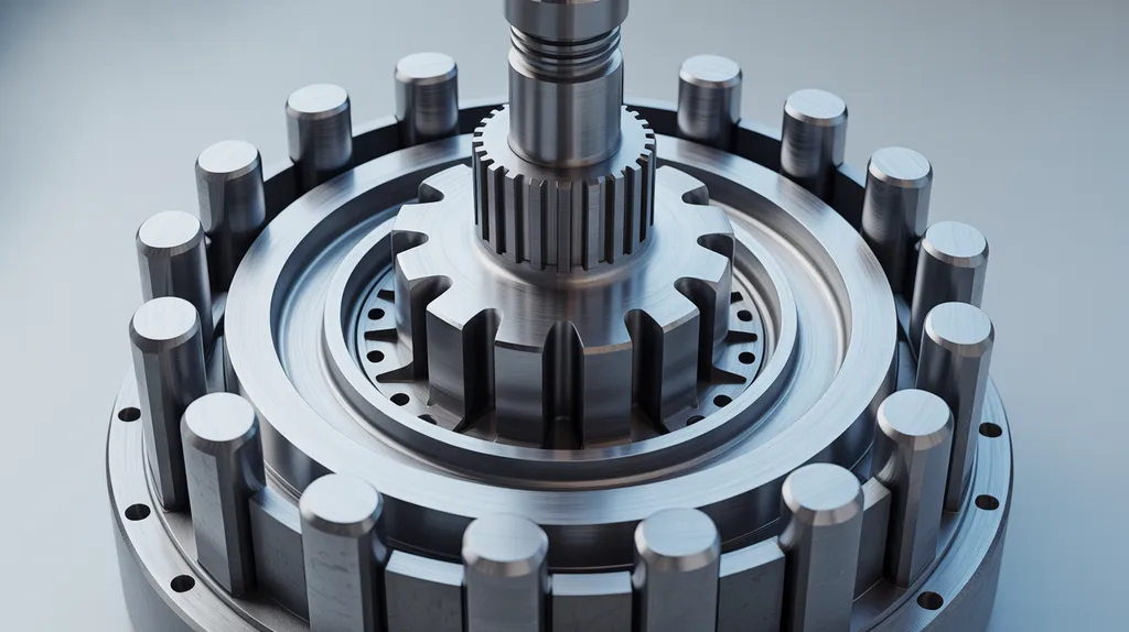
A cycloidal gearbox — also called a cycloidal drive or cycloidal speed reducer — is a mechanism that converts high-speed input into high-torque, low-speed output using an eccentric cam and a lobed disc that rolls through ring pins. Unlike gear teeth that mesh, the cycloidal disc rolls through the pins, creating rolling contact rather than sliding contact.
How it works in four steps:
- An eccentric cam (offset by 1–3 mm) rotates with the input shaft, causing the cycloidal disc to wobble in a circular motion.
- The disc has one fewer lobe than the number of ring pins in the housing; this difference creates the speed reduction.
- As the disc wobbles, the lobes push against the ring pins, transferring torque to the output shaft.
- The output shaft rotates in the reverse direction of the input at the reduced speed.
Because 60–70% of the disc's lobes share the load at any moment, the Hertzian stress on each contact point stays low. This load-sharing characteristic is the core reason cycloidal gearboxes survive shock loads that would damage conventional gear teeth.
What Is a Worm Gearbox?
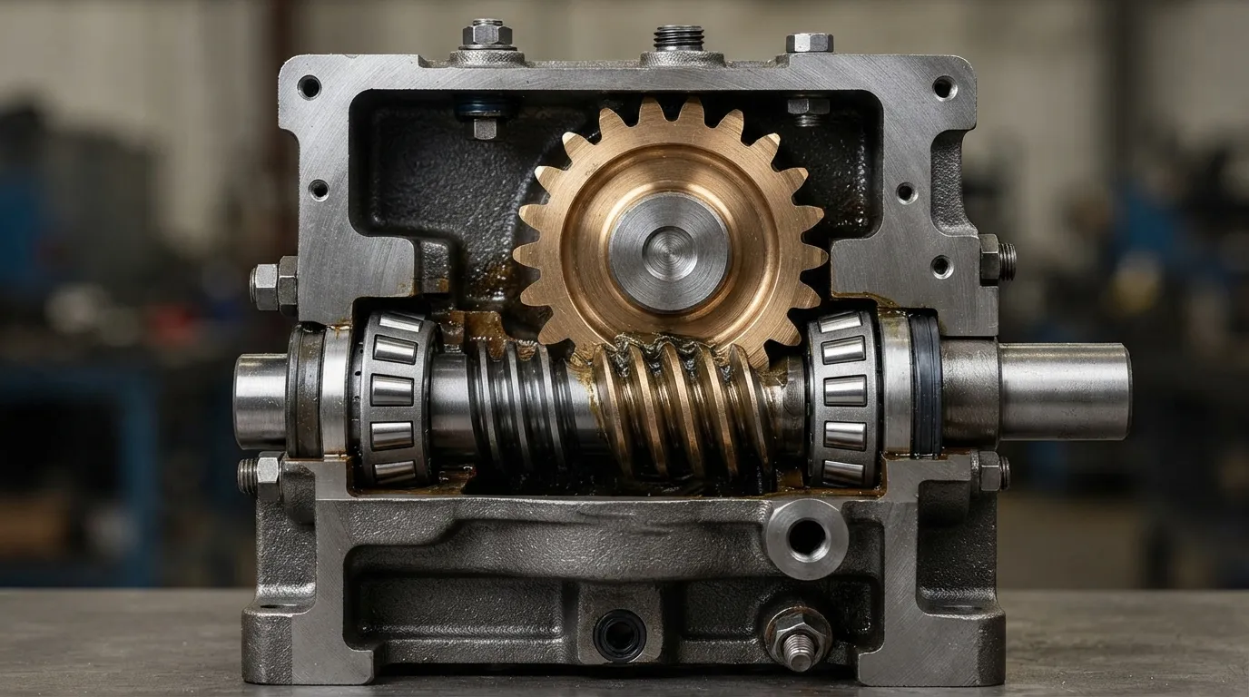
A worm gearbox — sometimes called a worm gear reducer — transmits power at a right angle using a threaded worm shaft that meshes with a worm wheel. The worm looks like a screw, and as it rotates, it pushes the worm wheel — but the contact between the two is sliding, not rolling.
How it works in three steps:
- The worm shaft (the input) rotates, and its threads engage the teeth of the worm wheel.
- Each full rotation of the worm advances the worm wheel by exactly one tooth.
- The worm wheel (the output) rotates at a right angle to the input shaft, at a reduced speed determined by the number of teeth.
The sliding contact that makes worm gearboxes compact and simple also creates friction and heat. That same friction produces the self-locking behavior that many applications rely on — but it also limits efficiency, which matters more as ratios increase. NMRV worm gear motors are a common variant of this design, used widely in light to medium industrial duty.
Cycloidal vs Worm Gearbox: Side-by-Side Comparison
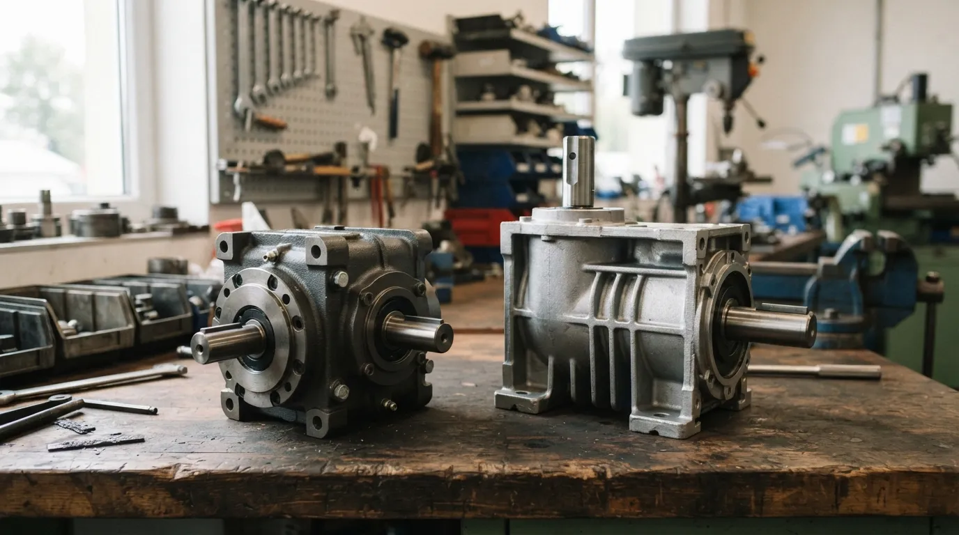
The table below summarizes the key differences across the decision criteria that matter most in industrial applications.
| Criterion | Cycloidal Gearbox | Worm Gearbox |
|---|---|---|
| Efficiency | 85–93% (single stage) | 70–85% (ratio-dependent) |
| Ratio range (single stage) | 10:1 to 200:1 | Typically up to 60:1 (higher with multiple stages) |
| Backlash | 0.1–0.2 arcmin (precision models) | Higher; not suited for precision positioning |
| Shock load capacity | Up to 500% of rated torque | Limited; vulnerable to peak loads |
| Self-locking | No | Yes (ratio and friction dependent) |
| Heat generation | Low (rolling contact) | High (sliding contact) |
| Service life | Longer; rolling contact wear | Shorter; worm wheel wear |
| Noise | Quiet, smooth operation | Moderate; can be noisier at high ratios |
| Maintenance | Bearing and lubrication care | Regular oil changes; worm wheel inspection |
| Cost factors | Higher initial cost | Lower initial cost |
| Configuration | Input/output shafts close, parallel offset | Right-angle standard |
This table shows the pattern clearly: cycloidal gearboxes dominate on performance criteria — efficiency, precision, shock tolerance, and life — while worm gearboxes win on cost and self-locking capability. The right choice depends entirely on which of these criteria matter most in your specific application.
Efficiency: Which Gearbox Wastes Less Energy?
Cycloidal gearboxes are significantly more efficient than worm gearboxes. According to Firgelli Automations, cycloidal drives achieve 85–93% efficiency in a single stage, which is "well above a worm gear at the same ratio." Independent longevity analysis from Eureka/Patsnap confirms the range, placing cycloidal drives at 85–90% efficiency and worm gears at 70–85%.
For a continuous-duty application running 24 hours per day, that 10–20% efficiency gap translates directly into energy costs. A cycloidal gearbox converts more of the motor's input power into useful output torque, while a worm gearbox dissipates more of it as heat.
What this means in practice:
- A 10% efficiency gain on a 5 kW motor running continuously saves roughly 4,380 kWh per year — a meaningful operating cost reduction.
- Higher efficiency means less heat in the gearbox, which extends lubricant life and reduces cooling requirements.
- Because worm gear efficiency drops as the ratio increases, the gap widens at higher reduction ratios.
Shock Load and Overload Capacity: Which Handles Impact Better?
Cycloidal gearboxes absorb shock loads that would damage a worm gearbox. According to Firgelli Automations, cycloidal drives can handle momentary shock loads up to 500% of rated torque without tooth breakage — and Nabtesco Precision Europe notes that emergency stop torque for cycloidal gearboxes reaches 500% of rated torque, with some cycloidal gearheads rated to 800%.
The mechanism behind this durability is load sharing. Because 60–70% of the cycloidal disc's lobes are in contact with ring pins at any moment, the force of a sudden impact is distributed across many contact points rather than concentrated on one or two gear teeth. This reduces stress on each individual surface.
Why cycloidal gearboxes survive shock loads:
- Multiple lobes share each impact simultaneously, lowering peak stress per contact point.
- The rolling contact between disc and pins is inherently more tolerant of momentary overload than sliding tooth contact.
- The disc and pins are made from hardened steel, resisting deformation under impact.
According to Transcyko, cycloidal gearboxes are suitable for "mission critical machinery, extreme working environments, sudden high torque loadings" — precisely the conditions found in mixers, crushers, conveyors, and other heavy industrial equipment.
The limit: A cycloidal gearbox is not indestructible. Sustained reverse shock above 500% of rated torque can crack the disc, and needle bearing collapse is a common failure when lubrication is neglected. But for genuine shock loads — momentary impacts, jammed equipment, start-stop cycles — cycloidal is the stronger choice.
Ratio Range and Backlash: Precision and Range Compared
Cycloidal gearboxes deliver a wider single-stage ratio range with better precision than worm gearboxes.
According to Firgelli Automations, cycloidal drives achieve ratios from 10:1 to 200:1 in a single stage. A worm gearbox, by contrast, typically achieves ratios up to 60:1 in a single stage — beyond that, multiple stages are required, which adds complexity, cost, and efficiency loss.
On precision, the difference is even more pronounced. Nabtesco Precision Europe reports that cycloidal gearboxes achieve pure backlash of 0.1–0.2 arcmin in their precision models, with a maximum hysteresis loss of 1 arcmin. For context, a standard planetary gearbox has roughly 3 arcmin of backlash, and a conventional planetary can reach 7 arcmin. Worm gearboxes are not typically specified for precision positioning at all because their sliding contact and wear characteristics make consistent, low backlash difficult to maintain.
Key specification comparison:
| Specification | Cycloidal Gearbox | Worm Gearbox |
|---|---|---|
| Single-stage ratio range | 10:1 to 200:1 | Up to ~60:1 |
| Backlash (precision models) | 0.1–0.2 arcmin | Not specified for precision |
| Hysteresis loss | Max 1 arcmin | Not specified for precision |
| Suitability for positioning | High | Low |
If your application requires accurate indexing, positioning, or repeatability — a rotary table, a robotic joint, a precision indexer — cycloidal is the clear choice.
Self-Locking: When Does It Matter?
Worm gearboxes are self-locking under the right conditions; cycloidal gearboxes are not. This is one of the most important application-driven differences between the two.
Self-locking means the gearbox cannot be backdriven — the output shaft will not rotate the input shaft when a load is applied. A worm gearbox is self-locking when the lead angle of the worm is small enough that the friction between the worm threads and the worm wheel teeth prevents reverse rotation.
When self-locking matters:
- Lifting and hoisting applications where the load must stay in position when power is removed
- Conveyor systems on an incline where the belt must not run backward
- Actuators and positioning devices that must hold position without a brake
- Safety-critical applications where unintended movement is unacceptable
Important caveats about self-locking:
- Self-locking is not guaranteed at all ratios. As a rule of thumb, higher ratios are more reliably self-locking than lower ones.
- The self-locking property depends on the coefficient of friction, which changes with wear, lubrication, and contamination.
- A "self-locking" worm gearbox that is worn, poorly lubricated, or contaminated may no longer hold position reliably.
- Always verify self-locking behavior for your specific ratio, lubrication, and operating conditions rather than assuming it is inherent.
A cycloidal gearbox, by contrast, can always be backdriven. If you need a load to hold position without a brake, a worm gearbox is the safer choice — but confirm the actual behavior with the manufacturer for your specific configuration.
Heat and Service Life: Which Runs Cooler and Lasts Longer?
Cycloidal gearboxes run cooler and last longer than worm gearboxes because of their rolling contact design. This is not a minor difference — it affects duty cycle, maintenance intervals, and total cost of ownership.
According to the Eureka/Patsnap longevity analysis, cycloidal drives operate for more than 20,000 hours under typical conditions, while worm gearboxes typically last 10,000–15,000 hours. The difference comes down to the fundamental contact mechanics:
| Criterion | Cycloidal Gearbox | Worm Gearbox |
|---|---|---|
| Operating hours (typical) | >20,000 hours | 10,000–15,000 hours |
| Heat generation | Low (rolling contact) | High (sliding contact) |
| Primary wear mode | Bearing wear, lubrication degradation | Worm wheel tooth wear, scoring |
The sliding contact in a worm gearbox generates significantly more heat than the rolling contact in a cycloidal design. At high ratios, worm gear efficiency can approach 50%, meaning roughly half the input power is lost as heat. This heat must be dissipated, which often requires:
- Lower allowable duty cycles (for example, 30–50% duty instead of continuous operation)
- Larger gearbox frames to dissipate heat
- External cooling fans, oil coolers, or heat exchangers in demanding applications
- More frequent oil changes to manage thermal degradation of the lubricant
A cycloidal gearbox, running cooler, can operate continuously at full rated load with standard lubrication and longer service intervals. For applications that run around the clock — mixers, conveyors, agitators — this difference is decisive.
Applications: Where Each Gearbox Excels
The application determines the right technology — not the other way around.
Best for cycloidal gearboxes:
- Continuous-duty equipment: mixers, agitators, paddle mixers, and conveyor drives that run for long periods
- Shock-loaded machinery: crushers, shredders, conveyors with heavy or irregular loads, and equipment subject to jams
- Precision applications: rotary tables, indexing equipment, robotics, and positioning systems that need low backlash
- High-ratio requirements: applications needing ratios above 60:1 in a compact single-stage package
- Mission-critical operations: equipment where downtime is expensive and reliability is non-negotiable
Real-world examples from Firgelli Automations include belt conveyors at Amazon fulfilment centres driven by Sumitomo Cyclo BBB4 gearboxes under shock loads, and FANUC R-2000iC robot wrist and elbow joints using Nabtesco RV-series cycloidal reducers for 100:1+ ratio and zero-backlash positioning.
Best for worm gearboxes:
- Light-duty intermittent operation: small conveyors, actuators, and adjustment mechanisms
- Self-locking requirements: lifting devices, hoists, and position-holding applications
- Right-angle layouts: where the motor must sit at 90° to the output shaft and space is tight
- Budget-sensitive projects: where initial cost matters more than long-term efficiency
- Applications with low precision requirements: where backlash and positioning accuracy are not critical
Mingye supplies both cycloidal pinwheel reducers and NMRV worm gear motors, and serves OEMs and plant engineers across plastics and rubber, mixing, conveying and material handling, packaging, mining, cement, power, and ports. Having access to both technologies means application fit can guide the specification honestly.
How to Choose: A Simple Decision Rule
Answer these four questions in order, and the right technology becomes clear:
Step 1 — Load type. Does your application involve shock loads, reversing loads, or frequent start-stop cycles? If yes, choose cycloidal. Steady, light, and predictable loads may be fine with worm.
Step 2 — Duty cycle. Is the equipment running continuously (8+ hours per day, or around the clock)? If yes, choose cycloidal — the efficiency advantage and lower heat generation will justify the higher initial cost. Intermittent or short-run operation may be well served by a worm gearbox.
Step 3 — Precision requirement. Do you need accurate positioning, low backlash, or repeatable indexing? If yes, choose cycloidal. If positioning accuracy is not critical, worm may be adequate.
Step 4 — Self-locking. Must the load hold position when power is removed, without a brake? If yes, a worm gearbox may be the right choice — but verify that your specific ratio and configuration are truly self-locking under your operating conditions.
Step 5 — Budget and package constraints. If initial cost is the dominant factor and the application is light duty, worm gearboxes are the economical choice. If you are evaluating long-term total cost of ownership — energy, maintenance, downtime, and replacement intervals — cycloidal gearboxes typically win.
When in doubt, work through a more detailed selection process. Our guide on how to choose a cycloidal reducer walks through the load classification and service factor calculations in more depth, and the cycloidal gearbox applications page shows where this technology delivers the strongest results across industries.
A Note on Mingye's Gearbox Ranges
Mingye designs and builds both cycloidal pinwheel reducers and NMRV worm gear motors in its own CNC-equipped factory in Shanghai. The company covers more than 20 gearbox and gear motor series, with modular, standardized designs that support OEM customization of mounting dimensions and transmission ratios.
Because Mingye manufactures both technologies rather than pushing a single product line, the selection can be matched to the actual application requirements. Typical delivery is 7–15 days, and the engineering team can help confirm self-locking behavior, shock load ratings, and service factors for your specific duty — but the final technology decision should always start with the application, not the product catalogue.
FAQ
Are cycloidal gearboxes worth the higher cost?
For continuous duty, shock-loaded, or precision applications, yes — the 10–20% efficiency gain and longer service life (over 20,000 hours versus 10,000–15,000 for worm) typically offset the higher initial cost within a few years of operation. For light, intermittent duty, worm gearboxes remain the economical choice.
Can a worm gearbox be backdriven?
Yes, but only when the lead angle exceeds the friction angle — generally at low ratios. Below a threshold, worm gearboxes self-lock and cannot be backdriven. Wear and lubrication state also affect backdriveability, so verify the behavior for your specific ratio rather than assuming it.
What maintenance do cycloidal gearboxes require?
Cycloidal gearboxes need periodic lubrication checks and bearing condition monitoring. The most common failure modes are needle bearing collapse (from lubrication failure) and pin galling (from contaminated grease). Regular oil changes at manufacturer-specified intervals and contamination control extend service life significantly.
Which gearbox is quieter, cycloidal or worm?
Cycloidal gearboxes operate more quietly and smoothly because the rolling contact between the disc and pins produces less vibration than the sliding contact in a worm gearbox. Worm gearboxes can become noisier at higher ratios as friction and vibration increase.
Share on Social:


Contact Us
In This Article
Right Angle Geared Motor: Matching Electrical Supply, Variable Speed and Braking
Oct 26, 2026
Planning a Bevel Reducer Installation: Turn Shaft Requirements Into a Practical Drive Layout
Oct 26, 2026
Choosing an Overhead Crane Gearbox by Its Hoisting or Travel Function
Oct 26, 2026
Replacing an Industrial Worm Gearbox: What to Keep and What to Reassess
Oct 25, 2026