


 Home /
Why Are Cycloidal Gearboxes Used in Robotics?
Rubber Internal Mixer Gearbox: Read the Batch Load Profile, Not Just Motor kW
Oct 22, 2026
Hot Industrial Gearbox Coupling After Cold Alignment: What to Check
Oct 22, 2026
Hydraulic Slewing Drive Won't Rotate: Separate Motor, Brake and Gearbox Faults
Oct 22, 2026
Calender Roll Gap Changes: What Must the Drive Coupling Accommodate?
Oct 22, 2026
Cycloidal gearboxes are used in robotics because they deliver high reduction ratios (30:1 to 300:1) in a single compact stage with extremely low backlash, high torsional stiffness, and exceptional shock-load tolerance — precisely what robotic joints need for precise, repeatable motion under variable loads. Their multi-tooth rolling contact distributes force across many surfaces, so they survive the abrupt starts, stops, and direction reversals common in robotic operation.
Key Takeaways
- Cycloidal gearboxes achieve single-stage ratios from 30:1 to 300:1 with backlash as low as ≤1 arcmin, enabling precise robotic joint positioning.
- Multi-tooth rolling contact distributes load across many surfaces, giving cycloidal drives shock-load tolerance up to 5 times nominal torque — ideal for robotic start/stop and jam events.
- The eccentric cam design with rolling contact minimizes wear and backlash while maximizing stiffness, outperforming planetary gearboxes under shock loads.
- Cycloidal drives dominate high-payload industrial robots; harmonic drives remain preferred for lighter robots (1–20 kg payload) where precision-to-weight ratio matters most.
What Is a Cycloidal Gearbox?
A cycloidal gearbox is a compact speed reducer that uses an eccentric cam to orbit one or two cycloidal discs against stationary ring pins, converting high-speed input into high-torque, low-speed output through rolling contact. It is one of the three main gear types used in industrial robots, alongside strain wave (harmonic) drives and planetary gear drives.
The cycloidal gearbox belongs to a family of power transmission components that serve industrial automation, material handling, and process machinery. Beyond robotics, cycloidal gearboxes are widely used across many industrial applications where compact, high-torque reduction is required.
How Does a Cycloidal Gearbox Work?
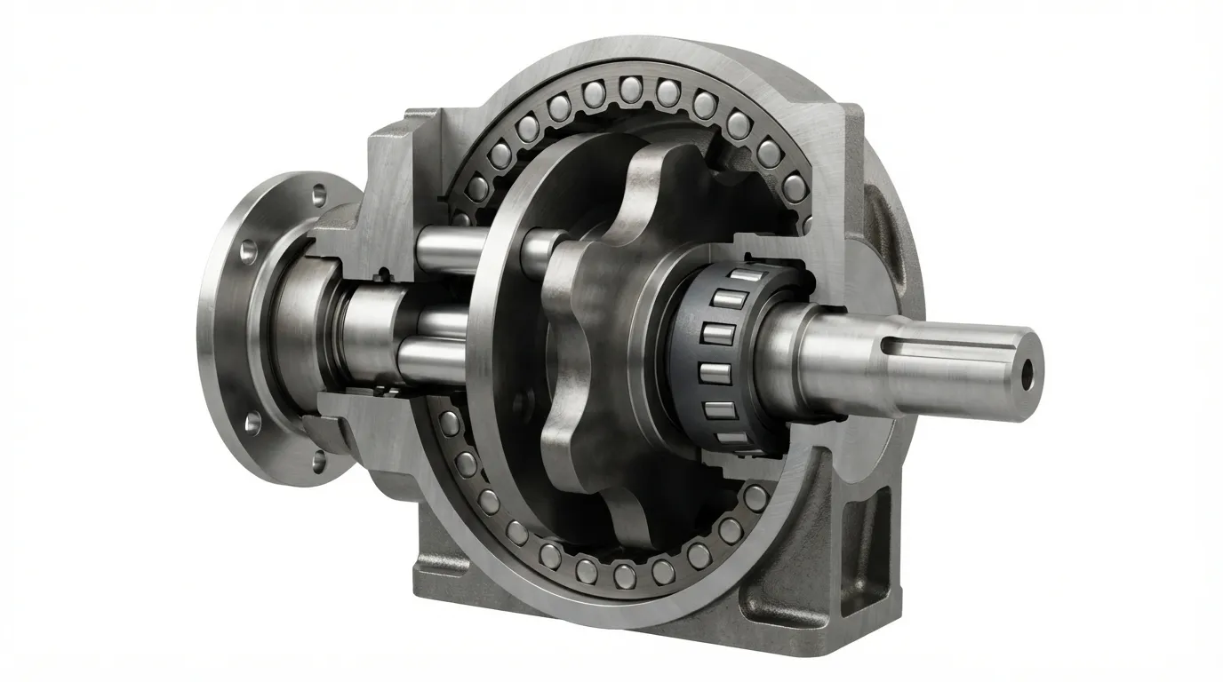
A cycloidal gearbox works by converting the rotating motion of an input shaft into the slower, higher-torque orbital motion of one or more cycloidal discs, which then drive an output shaft through a set of output pins.
The working principle follows these steps:
- Input shaft rotation: The input shaft turns an eccentric bearing mounted at its center.
- Eccentric cam motion: The eccentric bearing forces the cycloidal disc to orbit rather than simply rotate, creating an off-center circular motion.
- Cycloidal disc engagement: As the disc orbits, its lobed profile engages with stationary ring pins fixed to the gearbox housing.
- Pin-by-pin advance: Each full orbit of the disc advances the engagement point by one lobe, forcing the disc to rotate slightly in the opposite direction.
- Output pin extraction: Output pins, positioned through holes in the disc, capture this slow rotation and transfer it to the output shaft.
- Ratio generation: The reduction ratio equals the number of lobes on the disc, creating the speed reduction.
According to IMSystems, if there are 11 stationary pins and 10 lobes on the cycloidal disc, the output speed is reduced by a factor of 10, and output torque is increased tenfold. This single-stage design achieves ratios from 30:1 up to 300:1.
One design consideration: the orbital motion of the cycloidal disc creates vibration. Engineers compensate with dual-disc setups, where two discs are mounted 180 degrees apart to cancel each other's imbalance, though this increases size and weight.
Why Are Cycloidal Gearboxes Used in Robotic Joints?
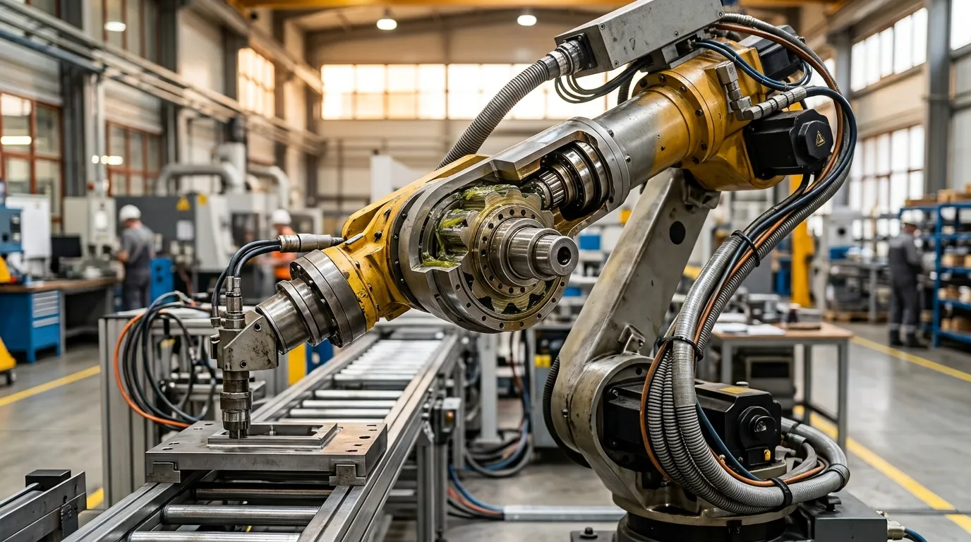
Robotic joints demand high torque density, minimal backlash, high stiffness, and resilience to shock loads in a compact package — cycloidal gearboxes provide all four through their unique multi-tooth rolling contact design.
According to Cone Drive, cycloidal drives handle high torque with minimal backlash and are used in robotic arms, actuators, and motion control systems where compactness and high-performance gear reductions are required. The rolling contact between cycloidal gear teeth reduces wear risk, enabling heavy loads without failure.
The table below maps the design features of cycloidal gearboxes to the specific benefits they deliver in robotic joints:
| Design Feature | How It Works | Robotic Benefit |
|---|---|---|
| Eccentric cam + cycloidal disc | Compact single-stage high ratio | High reduction in tight joint envelope |
| Multi-tooth rolling contact | Load distributed across many surfaces | High torsional stiffness, shock tolerance |
| Rolling contact (not sliding) | Minimal wear, no tooth gap | Near-zero backlash persists over life |
| Dual-disc design | Counter-rotating discs cancel vibration | Smooth motion at varying speeds |
The multi-tooth meshing is the defining advantage. When a robotic arm changes direction under heavy load, the cycloidal gearbox spreads the load across many rolling surfaces simultaneously. As one robotics expert noted, this provides "high torque, smooth movement, and almost zero backlash" even during rapid direction reversals. A planetary gearbox under the same conditions would concentrate stress on a single gear tooth, risking damage.
What Are the Disadvantages or Limitations of Cycloidal Gearboxes?
Cycloidal gearboxes have drawbacks — vibration from orbital motion, higher cost than planetary units, and limited backdrivability at high ratios — but these are acceptable trade-offs in high-payload robotic joints where precision and durability matter more.
The main limitations and their engineering context:
- Vibration: The orbital motion of the cycloidal disc creates inherent vibration. The dual-disc design reduces but does not eliminate this; robotic designers must account for it in high-speed axes.
- Cost: According to Cone Drive, cycloidal gears are generally more expensive to manufacture than planetary alternatives. However, they offer long-term savings through durability, reduced maintenance, and higher efficiency in demanding applications.
- Backdrivability limitations: At high reduction ratios, friction and the eccentric mechanism make backdriving difficult. This is a safety advantage for load-holding but limits energy-recovery applications.
- Complexity: The precision machining required for cycloidal discs and eccentric components makes them more complex to manufacture than simple planetary gear sets.
For engineers comparing cost across gearbox types, understanding the total cost of ownership matters more than the initial purchase price in robotic applications.
Can You Backdrive a Cycloidal Gearbox?
Some cycloidal gearboxes can be backdriven at lower reduction ratios, but friction and the eccentric mechanism make backdriving difficult at higher ratios — a useful property for load-holding but a limitation for energy recovery or compliant motion.
According to IMSystems, at lower gear ratios, some cycloidal drives can be backdrivable, allowing energy recovery and compliance in robotic systems. This means the gearbox can be driven from the output side under certain conditions. However, as the reduction ratio increases, the internal friction and the mechanical advantage of the eccentric mechanism combine to resist reverse motion.
For robotic designers, this conditional backdrivability is a double-edged sword:
- Advantage: High-ratio cycloidal gearboxes hold loads firmly when power is removed, acting as a brake without additional hardware.
- Limitation: The gearbox cannot be used for energy recovery in regenerative systems, and it will not provide the backdrivable compliance needed for certain collaborative or force-controlled applications.
Cycloidal vs Harmonic Drives in Robotics
Harmonic drives dominate lightweight robot arms (1–20 kg payload) where precision-to-weight ratio is critical; cycloidal gearboxes excel in high-payload robots where shock tolerance, stiffness, and durability under heavy loads are paramount.
According to Frontiers in Robotics and AI, the main types of gears used in industrial robots are strain wave drives (commonly called harmonic drives), cycloidal drives, and planetary gear drives. The choice among them depends on the robot's payload class and operating conditions.
| Attribute | Cycloidal Gearbox | Harmonic Drive |
|---|---|---|
| Reduction ratio | 30:1–300:1 single stage | High (typical 50:1–160:1) |
| Backlash | ≤1 arcmin possible | Near-zero |
| Torque density | Excellent | Excellent (lighter) |
| Shock-load tolerance | Excellent (up to 5x nominal) | Moderate (flexspline fragile) |
| Vibration | Some (orbital motion) | Low |
| Cost | Higher than planetary | Higher than planetary |
| Best payload range | High-payload robots | 1–20 kg robots |
| Maintenance | Low wear, durable | Flexspline fatigue over time |
A clear pattern has emerged in industrial robotics: cycloidal gears are widely used in high-payload robots, while strain wave or harmonic drives dominate many robot joints in lower-payload robots (1–20 kg). The harmonic drive's lighter weight and near-zero backlash make it attractive for small, fast, precise arms. Cycloidal gearboxes become the preferred choice when the robot must handle heavier loads, survive shock events, and maintain precision over a longer service life.
For a more detailed comparison of these two drive types, see our guide on cycloidal gearbox vs harmonic drive.
Cycloidal vs Planetary Gearboxes in Robotics
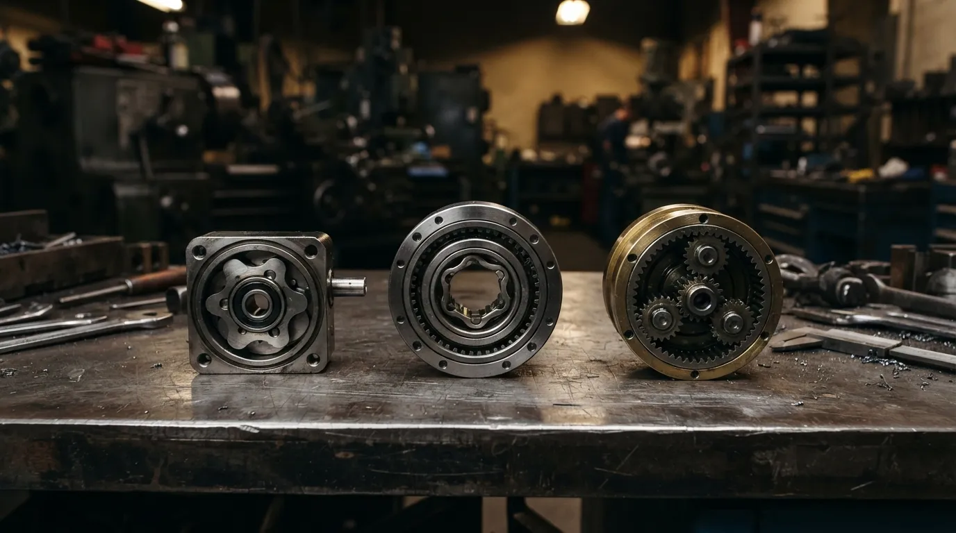
Planetary gearboxes offer lower cost, higher efficiency, and lower vibration, but cycloidal gearboxes are the standard choice when a planetary unit would survive steady-state loads yet fail from shock loads, startup jams, or frequent direction reversals.
As Firgelli explains, the cycloidal drive is "the standard choice when a planetary gearbox would survive the steady-state load but get its teeth chipped by a startup or jam event." This distinction is critical for robotic applications where the joint frequently starts, stops, reverses, or encounters resistance.
| Attribute | Cycloidal Gearbox | Planetary Gearbox |
|---|---|---|
| Reduction ratio | 30:1–300:1 single stage | 3:1–100:1 per stage |
| Backlash | ≤1 arcmin possible | 3–10 arcmin typical |
| Shock-load tolerance | Excellent (up to 5x nominal) | Moderate (gear tooth chipping) |
| Torque density | Higher per weight | Lower per weight |
| Efficiency | Good, slightly lower | Excellent |
| Vibration | Some (orbital motion) | Low |
| Cost | Higher | Lower |
| Best use | Shock loads, high precision | Steady loads, high speed |
Planetary gearboxes are the right choice when the load is predictable, the speed is high, and cost efficiency is a priority. Cycloidal gearboxes justify their higher cost when the joint must absorb shock loads, maintain extremely low backlash, or operate for years without backlash-related maintenance.
For an in-depth technical comparison of these two designs, see our planetary vs cycloidal gearbox analysis.
How to Select a Cycloidal Gearbox for a Robot Joint
Select a cycloidal gearbox by specifying reduction ratio, backlash, torsional stiffness, continuous and peak torque, speed, and mounting configuration — in that order of priority for most robotic joints.
The selection process follows a logical sequence:
- Determine the reduction ratio needed to match motor speed to the required joint speed. Single-stage cycloidal gearboxes cover 30:1 to 300:1.
- Specify backlash tolerance based on positioning accuracy requirements. For high-precision robotic applications, aim for backlash below 3 arc-minutes (0.05 degrees), according to Arctos Robotics.
- Calculate torsional stiffness requirements based on the load and the acceptable deflection under peak torque.
- Define continuous and peak torque for the application. For reference, the GAM GCL series of robotic cycloidal gearboxes offers nominal torque from 167 to 4410 Nm across its size range.
- Check speed ratings — cycloidal gearboxes have maximum input speeds that must not be exceeded.
- Confirm size and weight constraints for the robot joint envelope.
- Select mounting configuration — flange, shaft, or hollow-bore options must match the joint design.
- Review efficiency and cost trade-offs against the application's duty cycle.
For detailed guidance on the selection process, see how to choose a cycloidal reducer.
Final Verdict — When to Choose Cycloidal Over Harmonic or Planetary
Choose cycloidal for high-payload robots, shock-prone axes, or when long service life with minimal maintenance is critical; choose harmonic for lightweight precision arms; choose planetary for steady-state, cost-sensitive applications.
Three decision rules summarize the engineering guidance:
- Choose cycloidal when: The robot handles high payloads, the joint experiences shock loads or frequent direction reversals, or the application requires backlash below 3 arc-minutes with long service life.
- Choose harmonic (strain wave) when: The robot is in the 1–20 kg payload class, weight is critical, and the application demands near-zero backlash in a lightweight package.
- Choose planetary when: The load is steady, shock events are rare, speed is high, and initial cost is the primary constraint.
The cycloidal gearbox earns its place in robotic joints because it solves the hardest engineering problem in robot motion: combining high reduction, high precision, and high durability in a compact package that can survive the real-world abuse of industrial operation.
Mingye designs and manufactures cycloidal pinwheel reducers and other power transmission equipment in its own CNC-equipped factory. For engineering guidance specific to your robotic joint design, contact the Mingye team.
Share on Social:


Contact Us
In This Article
Rubber Internal Mixer Gearbox: Read the Batch Load Profile, Not Just Motor kW
Oct 22, 2026
Hot Industrial Gearbox Coupling After Cold Alignment: What to Check
Oct 22, 2026
Hydraulic Slewing Drive Won't Rotate: Separate Motor, Brake and Gearbox Faults
Oct 22, 2026
Calender Roll Gap Changes: What Must the Drive Coupling Accommodate?
Oct 22, 2026