


 Home /
Right Angle Gearbox Selection: From Machine Layout to Confirmed Drive Specification

Right Angle Geared Motor: Matching Electrical Supply, Variable Speed and Braking
Oct 26, 2026

Planning a Bevel Reducer Installation: Turn Shaft Requirements Into a Practical Drive Layout
Oct 26, 2026

Choosing an Overhead Crane Gearbox by Its Hoisting or Travel Function
Oct 26, 2026

Replacing an Industrial Worm Gearbox: What to Keep and What to Reassess
Oct 25, 2026
Although a right angle gearbox can be used for a crowded machine layout, a compact housing alone is not sufficient to make a drive suitable. The unit should also provide the necessary movement, withstand the operating cycle and integrate the unit properly with other equipment.
The valuable starting place for OEM engineers and industrial buyers is an application brief. This guide is designed to explain how to convert a drive requirement of 90° to a specification which Mingye can review, quote and confirm prior to manufacture or supply.
Specify the Drive Must Fit Space
A right angle gearbox is used for transmitting power from an axis to a right-angle axis. Depending on the design, those axes can either overlap or they offset. This difference is important when installing a motor in a location next to a conveyor roll, below a processing machine or near a limited access aisle.
Start with a drawing of the complete drive envelope. Include motor, terminal box, motor coupling, guards, mounting structure and access to remove parts. Measure output shaft position to machine fixed points. A gearbox that clears the frame may still block a guard and/or provide inadequate clearance for maintenance.
Note the difference between a stand alone reducer, and one that is part of a gear motor supplied as an assembly. This selection determines motor matching, interface size and the range of purchase.
Select the Gear Pattern around the Duty
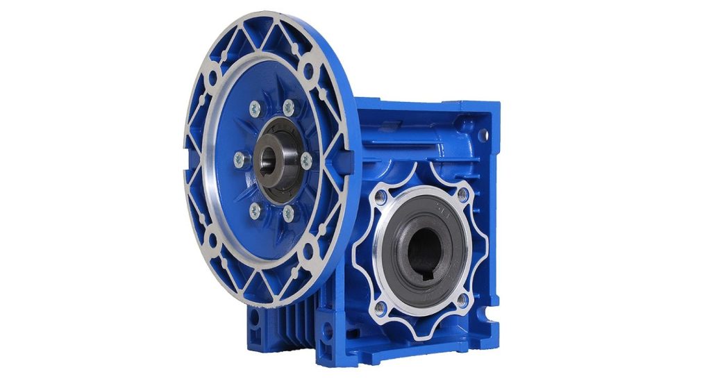
Right-angle is a term to denote geometry, not one gear mechanism. Mingye's RV Series Worm Gear Motor is a compact square housing type worm gear motor. It is a pertinent beginning point for which the packaging space and speed reduction are key demands. Even then its suitability is dependent on the ratio chosen, load, speed at the input and temperature.
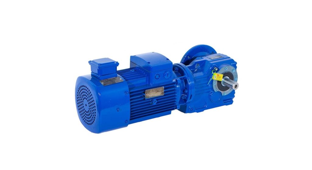
The K Series Helical Bevel Gear Motor can be used for continuous industrial drives. It's a mixture of helical and bevel gearing and will deal with reduction and directional energy transfer. This type of worm layout has an efficiency benefit over a similar worm layout, but losses will vary depending on the operating point.
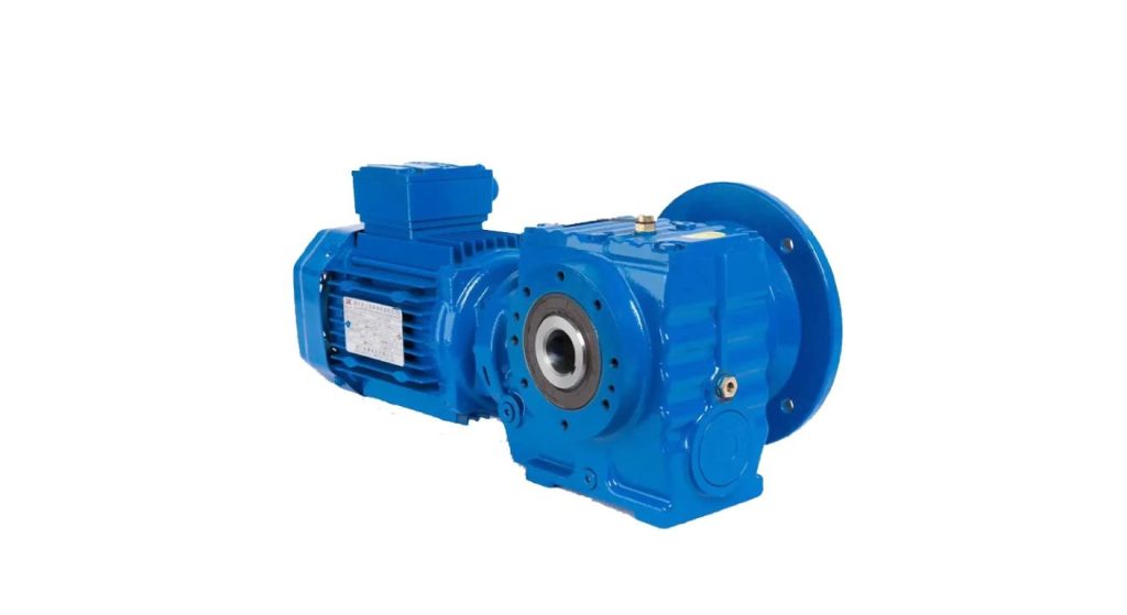
Mingye also provides S Series Helical Worm Gear Motor which is based on the combination of helical gearing and worm stage. Consider it to be its own configuration rather than assume that it shares all the properties of either alternative. Compare candidates at the same required output duty with dimensions and ratings given.
Set the Machine's Motion.
Before choosing the motor power, select the required output speed and running torque. Ratio is input speed / output speed. For example, if the input speed is 1,500 rpm and the output is 50 rpm then the ratio is 30:1, but the actual output depends on the gearbox ratio that is used and the actual motor speed.
Next explain startup, speed up, turn around and stop. Conveyor restarting under a material accumulation can provide a different demand than an empty conveyor operating at steady state. Don't conceal these events in an oversized motor selection, but tell the supplier when they occur, the length of time they last and the magnitude of the torque when they happen.
Where a frequency converter is used to modify the speed of the motor, supply the complete range of operation. Check motor cooling and gearbox lubrication at the desired motor speed. The nominal operating point is not suitable for the entire machine cycle.
Check Heat and Shaft Loads Individually
Mechanical torque capacity and thermal capacity are questions of different things. The torque required for a reducer may be transmitted but, during prolonged use, the amount of heat created may be greater than the heat that can be dissipated by the reducer installation. Ambient temperature, hours of operation per day, enclosure conditions and starts per hour shall be provided to allow the supplier to evaluate the actual duty.
Other shaft loading must also be considered. A chain sprocket or belt pulley has forces other than the transmitted torque. Because it is not always located at the same distance from the gearbox bearing, send the dimensions and position it is in rather than just the shaft diameter.
When mounting the machine on a hollow shaft, check the machine shaft fit and reaction arrangement. Inspect for alignment and support (coupled drives). Do not use the gearbox to make up for the lack of support of the machine shaft or a distorted mounting frame.
Accept the Mounting and Lubrication in Unison
Include the mounting location as a part of the specification. Changing a reducer to a convenient bracket will change the lubrication arrangement, amount of oil and location of service points. Get directions for the specific direction(s) provided.
Mingye's right angle gear motor mounting guide covers solid and hollow shafts, foot and flange mountings and reaction torque. Before the machine frame is finalized use the approved dimensional drawing to resolve these interfaces. Check shaft projection, keyway, flange register, bolt pattern and direction of view for describing rotation.
Arrange access for inspection and maintenance in installed machine. If an oil service point is located behind a welded panel, it can cause a long shutdown under normal circumstances. Use one lubricant schedule for each model, and be sure to agree on lubricant and service requirements for the model being used, not for all reducer families.
Attach Manufacturing Evidence to Selected Product.
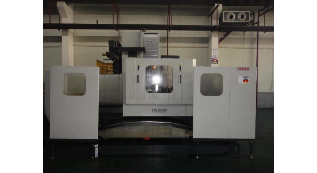
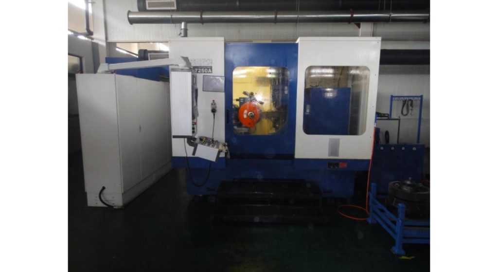
A supplier review which includes manufacturing information to the proposed gearbox is useful. The Mingye's K-series product page includes a description of housing machining, gear cutting, carburizing and quenching, gear grinding, dimensional inspection and tooth inspection. The relevance to these processes should be verified with the configuration ordered as these processes cover different sources of variations.
Inquire about what inspection records and dimensional documents you are being provided with that configuration. For reordering an OEM item, retain the approved Drawing Revision and Ordering Code. Later, if the motor, or shaft arrangement, or mounting position, or ratio changes, consider the affected interfaces again – don't assume that the revised unit is interchangeable.
To send an Application Brief That Can Be Confirmed.
Collate layout drawing, operating profile and interface requirements before asking for a quotation. Make sure that the supplier knows clearly which items are not yet resolved, which are assumptions. Request confirmation of proposed model, rating basis, mounting and lubrication documentation.
Store this confirmation in a place easy to find by the team that is constructing the machine, so that purchasing and installation can be done in the same agreed configuration and to the same document revisions.
There is no universal answer to whether a right angle gearbox will work; it's a matter of geometry, motion, and installation. An application brief that is short and concise provides the purchasing and engineering with the same reference, which helps avoid a correct manufactured reducer being the wrong machine drive.
| Approval Item | Record to Keep | Review Trigger |
| Drive configuration | Complete model and motor code | Ratio or motor change |
| Machine interface | Approved dimensional drawing | Shaft or frame revision |
| Operating limits | Confirmed duty and rating basis | Load or cycle change |
| Installation instructions | Mounting code and lubrication document | Orientation or environment change |
FAQs
Q1. Are all the right angle gearboxes worm gearboxes?
Right angle transmission can be provided by No Worm, Helical Bevel and Helical Worm arrangements. Choose the mechanism (the part around the app) instead of the outside housing form.
Q2. Is this necessarily the case if the reduction ratio is higher?
No, usable output is restricted by the rating of the gearbox, input power, losses and operating conditions. Verify proposed model at the specified speed/duty.
Q3. Does a worm gearbox require a brake if it is used to hold up a load?
Do not assume this. The back-driving behaviour is a function of design and operating conditions: For applications in which secure holding is required, an appropriately designed brake or restraint is required.
Q4. Is it possible to install at a different location after delivery?
Once confirmed with supplier. Lubrication quantity, service points, or other installation details may have to be modified depending upon the different orientation.
Q5. Which of the following should be included in a request for quotation?
Include a layout drawing, desired output motion, desired duty cycle and shaft interface information. Add motor parameters and environmental restrictions to be able to verify the proposed assembly as a whole drive.
Share on Social:


Contact Us
In This Article
Right Angle Geared Motor: Matching Electrical Supply, Variable Speed and Braking
Oct 26, 2026
Planning a Bevel Reducer Installation: Turn Shaft Requirements Into a Practical Drive Layout
Oct 26, 2026
Choosing an Overhead Crane Gearbox by Its Hoisting or Travel Function
Oct 26, 2026
Replacing an Industrial Worm Gearbox: What to Keep and What to Reassess
Oct 25, 2026