


 Home /
Right Angle Gear Motor Mounting Guide: Hollow Shaft, Solid Shaft, Flange, Foot and Reaction-Torque Considerations

Right Angle Geared Motor: Matching Electrical Supply, Variable Speed and Braking
Oct 26, 2026

Planning a Bevel Reducer Installation: Turn Shaft Requirements Into a Practical Drive Layout
Oct 26, 2026

Choosing an Overhead Crane Gearbox by Its Hoisting or Travel Function
Oct 26, 2026

Replacing an Industrial Worm Gearbox: What to Keep and What to Reassess
Oct 25, 2026
A maintenance team installs a new right-angle gear motor on a mixer shaft. The model number matches, the ratio matches, the power matches. They bolt the foot mounting to the base plate, tighten the flange bolts for extra security, and start the machine. Within two weeks, the bearings begin to growl. By the end of the month, the gearbox is leaking oil from the output seal. The problem is not the gear motor — it is the installation.
Right-angle gear motors fail in service more often from mounting errors than from gear or motor defects. This guide covers the mechanical interface decisions that determine whether a correctly specified unit will install cleanly and run reliably: shaft type selection, mounting method, reaction torque management, alignment, and the relationship between mounting position and lubrication.
Shaft Direction and Rotation: Define the Geometry First
Before anything else, establish the geometric relationship between the input (motor) shaft and the output (driven) shaft. In a right-angle gear motor, these shafts are perpendicular — but “perpendicular” is only the beginning.
Output Orientation
The output shaft can exit the gearbox in different directions relative to the motor:
- Horizontal output, motor horizontal: The most common configuration. The motor shaft and output shaft are both horizontal, but perpendicular to each other when viewed from above.
- Vertical output, motor horizontal: The output shaft points up or down while the motor sits horizontally. Common in agitators, screw conveyors, and lifting equipment.
- Other orientations: Depending on the gearbox design, the output can exit at various angles. The mounting position code (commonly M1 through M6) defines the standard orientations.
Rotation Direction
The output shaft rotation direction (clockwise or counterclockwise, viewed from the output shaft end) depends on the gear arrangement inside the gearbox. Two gear motors with the same ratio and power can have opposite output rotation directions. When ordering a replacement, always specify the required rotation direction — do not assume it from the model number alone.

Selecting a right-angle gear motor mounting configuration? Send the driven shaft diameter, available axial length, and a photo or sketch of the mounting surface. We can help confirm whether a solid shaft with coupling or a hollow shaft with torque arm is the better fit for your installation — before you order.
Solid Shaft vs. Hollow Shaft: Connection Method and Space
The choice between solid and hollow output shaft determines how the gear motor connects to the driven machine, how much space the drive package occupies, and how the reaction torque is managed.
Solid Shaft
A solid output shaft extends from the gearbox and connects to the driven machine through a coupling, sprocket, pulley, or direct connection.
Connection method: The driven component (coupling hub, sprocket, pulley) mounts on the solid shaft using a key and keyway. The shaft diameter, keyway dimensions, and shaft length must match the driven component’s bore and hub dimensions.
Alignment requirement: When using a coupling between the gearbox shaft and the driven shaft, the two shafts must be aligned — both radially (the shafts are concentric) and angularly (the shafts are parallel). Misalignment causes coupling wear, shaft fatigue, bearing overload, and vibration.
Alignment is checked using a straightedge and feeler gauges for basic applications, or dial indicators and laser alignment tools for precision applications. As a general guide: for low-speed or short-coupling-span applications, a straightedge may suffice; for high-speed or long-coupling-span installations, use dial indicators or laser tools to achieve the required precision. The alignment should be checked both cold (before operation) and warm (after the system reaches operating temperature), because thermal expansion can shift the alignment.
Space requirement: A solid shaft installation needs space for the shaft extension, the coupling (or sprocket/pulley), and the driven shaft. This is the traditional “inline” connection approach and requires more axial space than a hollow shaft installation.
Hollow Shaft
A hollow output shaft allows the driven machine’s solid shaft to insert directly into the gearbox bore, eliminating the need for a separate coupling.
Connection method: The driven shaft enters the hollow bore and is secured by one of two methods:
- Flat key (DIN 6885): A standard parallel key fits into keyways machined in both the driven shaft and the hollow bore. The shaft is held axially by a retaining nut and end cap. According to manufacturer documentation we have reviewed, some manufacturers require a threaded center hole (e.g., DIN 322 DS-type) at the shaft end for the retaining screw — confirm this requirement with your specific supplier.
- Shrink disc (expansion disk): A tapered sleeve fits between the driven shaft and the hollow bore. When the shrink disc bolts are tightened (in a cross-pattern, gradually and in multiple passes), the sleeve compresses onto the driven shaft, creating a friction-based, backlash-free connection. This method does not require a keyway on the driven shaft and provides uniform clamping force.
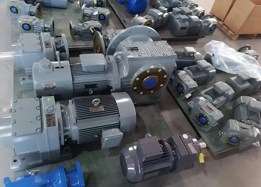
Shrink disc tightening guide: Tighten shrink-disc bolts only according to the specified sequence and torque in the manufacturer’s installation instructions. Clamping force and bolt torque vary by shrink-disc size and design — do not use generic torque values or tightening sequences.
Space advantage: A hollow shaft installation eliminates the coupling and its associated space, making the drive package more compact. This is particularly valuable in equipment where axial space is limited.
Alignment consideration: A hollow-shaft arrangement eliminates a separate coupling, but it does not eliminate the need to verify shaft fit, concentricity/runout, axial retention and reaction-torque restraint. The driven shaft must match the hollow bore diameter and keyway (if keyed), and the gearbox must be properly supported by its mounting interface or torque arm.
Disassembly consideration: Removing a hollow-shaft-mounted gearbox from the driven shaft may require a hydraulic puller or mechanical extraction tool, especially if the connection has been in service for a long time. Plan for disassembly access during installation design.
Hollow Shaft Does Not Mean “No Reaction Torque Management”
This is a common and costly misconception. When a gearbox is mounted directly on the driven shaft (hollow shaft configuration), the torque that the gearbox delivers to the shaft creates an equal and opposite reaction torque that tries to rotate the entire gearbox housing. This reaction torque must be absorbed by a torque arm, reaction bracket, or other mechanical link that connects the gearbox housing to the machine frame.
Without a torque arm, the gearbox will rotate around the driven shaft under load. This can damage the output shaft, the driven shaft, the seals, and potentially twist the motor cable. A shaft-mounted gearbox requires a verified method of restraining housing reaction torque, such as a torque arm or reaction bracket appropriate to the gearbox design. The torque arm must be:
- Rigid enough to resist the reaction torque without flexing
- Pinned or bolted to the machine frame at one end and to the gearbox housing at the other
- Designed with a pivot or flexible element if the driven shaft has any axial movement (thermal expansion, float)
Foot Mounting vs. Flange Mounting
Foot Mounting
The gearbox has foot castings (or a base flange) that bolt to a flat surface — typically a machine base plate or structural frame. This is the most straightforward mounting method and is used in the majority of industrial installations.
Considerations:
- The mounting surface must be flat and rigid. An uneven surface can distort the gearbox housing when the foot bolts are tightened, misaligning the gears and bearings.
- Check the bolt pattern (hole spacing, hole diameter) against the machine base before ordering.
- Use shims if needed to level the gearbox — but shims must be full-width (not partial) to distribute the load evenly.
Flange Mounting
The gearbox has a machined flange that bolts to a mating face on the machine. This is common when the drive is side-mounted or when the machine design has a vertical mounting face.
Considerations:
- The flange pilot (the machined spigot that locates the gearbox on the machine face) must match the mating bore. The pilot provides radial location; the bolts provide clamping.
- The flange must be rated for the combined weight of the gear motor and the reaction torque. A flange that is too small or too lightly bolted can flex under load.
- Flange mounting is often used when the gearbox is part of a modular system where drives are swapped or repositioned.
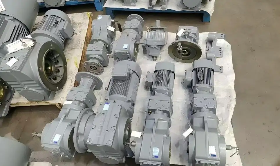
Foot and Flange: Follow the Manufacturer’s Installation Instructions
Some gearboxes provide more than one mounting interface (both foot and flange). Do not assume that all interfaces should be rigidly constrained simultaneously. If a gearbox provides more than one mounting interface, follow the installation instructions for the specific gearbox and mounting configuration. In some designs, using both foot and flange as rigid constraints can create competing constraints — the foot mounting tries to hold the gearbox in one position, and the flange mounting tries to hold it in another, which can distort the housing and misalign the gears and bearings.
Choose one mounting method based on the machine design. If the foot is used for primary location, leave the flange bolts loose or use the flange only as a pilot (location) without clamping. If the flange is used for primary mounting, leave the foot bolts out entirely.
Not sure whether to use foot mounting or flange mounting for your right-angle gear motor? Send a photo of the machine mounting surface and the available space. We can help determine which mounting method is appropriate and verify the bolt pattern and pilot dimensions before you commit to a specific model.
Keyway, Shaft Diameter, and Overhung Load
Keyway and Shaft Dimensions
When ordering or replacing a right-angle gear motor, capture the following shaft dimensions:
| Dimension | What to Measure |
| Output shaft diameter | Measure with calipers at the bearing journal |
| Output shaft length (usable) | The length of the shaft that engages the coupling or enters the hollow bore |
| Keyway width | Measure across the keyway |
| Keyway depth | Measure from the shaft surface to the bottom of the keyway |
| Hollow bore diameter (if hollow shaft) | The inside diameter of the hollow output shaft |
| Keyway in hollow bore (if keyed) | Width and depth of the internal keyway |
Standard keyway dimensions follow DIN 6885 or ANSI standards, but always measure the actual shaft — especially for replacement units, where the original manufacturer may have used non-standard dimensions.
Overhung Load (Radial Load)
When a solid output shaft drives a sprocket, pulley, or gear, the chain or belt tension creates a radial force on the output shaft — the overhung load. This force acts perpendicular to the shaft axis and loads the output bearing.
The overhung load depends on:
- The pitch diameter of the sprocket or pulley (smaller diameter = higher radial force for the same torque)
- The chain or belt tension (tighter = higher force)
- The weight of the sprocket or pulley itself
Why this matters: Every gearbox has a maximum permissible overhung load at the output shaft. Exceeding this load shortens bearing life, causes shaft deflection, and can lead to seal leakage. If your application uses a chain or belt drive on the output shaft, calculate the overhung load and compare it to the gearbox’s rated value. If the load is too high, use a larger sprocket (reduces chain tension per unit of torque), add an outboard bearing, or select a gearbox with a higher overhung load rating.
Mounting Position and Lubrication: The Hidden Dependency
The mounting position — the orientation of the gearbox relative to horizontal — directly affects the oil level inside the housing. Gearbox lubrication typically relies on a splash or bath system: the lower gears dip into the oil sump and splash oil to the upper bearings and gears. If the gearbox orientation changes, the oil level relative to the gears changes.
What This Means in Practice
- The mounting position must match the factory specification. If the gearbox was ordered for horizontal mounting (M1) and installed vertically (M4), the oil may not reach the gears properly — or it may flood the seals.
- Changing the mounting position requires adjusting the oil fill quantity. The manufacturer’s documentation specifies the correct oil volume for each mounting position code. If you change the orientation, you must drain and refill to the correct level for the new position.
- The breather (vent) must be at the highest point. The gearbox breather equalizes internal pressure as the air inside heats and cools. If the breather is below the oil level (because the gearbox was rotated), oil will leak out through the breather. When the mounting position changes, the breather location relative to the oil level changes — and the breather port may need to be repositioned to the new highest point.
- Vertical motor installation: When the motor shaft points vertically (up or down), take precautions to prevent liquids or contaminants from entering the motor along the shaft. This may require a rain cover or specialized shaft seal (some manufacturers designate this as an accessory type C — confirm the appropriate option with your supplier).
Mounting Position Codes
Most industrial gearbox manufacturers use a mounting position code, such as M1 through M6 in some manufacturer systems, to define the six basic installation orientations. These codes specify which side of the gearbox faces up, down, or sideways. Note that different manufacturers may use different naming conventions. When ordering, specify the mounting position so the factory fills the correct oil quantity, positions the breather correctly, and installs the correct seals for the orientation.
If you are replacing an existing unit and do not know the mounting position code, photograph the installed unit from multiple angles and note which surfaces are up, down, and horizontal. The supplier can determine the mounting position code from these photos.
Pre-Order Dimensional Checklist
Before placing an order for a right-angle gear motor, verify the following:
| Category | Item | Why It Matters |
| Shaft | Output shaft type (solid/hollow) | Determines connection method and coupling requirements |
| Shaft | Output shaft diameter and length | Must match driven component or driven shaft |
| Shaft | Keyway dimensions (width, depth) | Must match key or driven shaft keyway |
| Shaft | Hollow bore diameter (if applicable) | Must match driven shaft diameter |
| Mounting | Foot or flange (choose one) | Determines machine interface and bolt pattern |
| Mounting | Bolt pattern (hole spacing, hole size) | Must match machine base or face |
| Mounting | Center height (foot mount) | Must match machine base height |
| Mounting | Flange pilot diameter (flange mount) | Must match machine face bore |
| Mounting | Mounting position code (M1–M6) | Determines oil fill, breather position, seal type |
| Torque | Reaction torque management plan | Hollow shaft needs torque arm; solid shaft needs coupling |
| Load | Overhung load calculation (if sprocket/pulley) | Must be within gearbox rated radial load |
| Space | Overall envelope (length, width, height) | Must fit within machine space |
| Space | Maintenance clearance (oil drain, breather, bolts) | Must be accessible for service |
Specifying a right-angle gear motor installation? Send the driven shaft diameter, keyway dimensions, and available axial length. If this is a replacement, provide four photos: the nameplate, the output shaft, the mounting face (or foot), and the overall installation space — plus the key dimensions from the checklist above. We can confirm the correct mounting configuration and shaft interface before you order.
Summary: Three Rules That Prevent Most Mounting Failures
- Follow the manufacturer’s mounting instructions. If a gearbox provides more than one mounting interface, do not assume all should be rigidly constrained simultaneously. Follow the installation instructions for the specific gearbox.
- Hollow shaft requires reaction torque management. A torque arm or reaction bracket appropriate to the gearbox design is required to prevent the gearbox from rotating under load.
- Mounting position determines oil fill and breather location. If the orientation changes from the original specification, the oil quantity and breather position must be adjusted according to the manufacturer’s documentation.
Share on Social:


Contact Us
In This Article
Right Angle Geared Motor: Matching Electrical Supply, Variable Speed and Braking
Oct 26, 2026
Planning a Bevel Reducer Installation: Turn Shaft Requirements Into a Practical Drive Layout
Oct 26, 2026
Choosing an Overhead Crane Gearbox by Its Hoisting or Travel Function
Oct 26, 2026
Replacing an Industrial Worm Gearbox: What to Keep and What to Reassess
Oct 25, 2026