


 Home /
How to Choose the Right Gear Ratio for a DC Gear Motor: Speed, Torque, Efficiency, and Safety

Right Angle Geared Motor: Matching Electrical Supply, Variable Speed and Braking
Oct 26, 2026

Planning a Bevel Reducer Installation: Turn Shaft Requirements Into a Practical Drive Layout
Oct 26, 2026

Choosing an Overhead Crane Gearbox by Its Hoisting or Travel Function
Oct 26, 2026

Replacing an Industrial Worm Gearbox: What to Keep and What to Reassess
Oct 25, 2026
The basic gear ratio formula — motor speed divided by output speed — takes about ten seconds to apply. But the gap between a ratio that works on paper and one that works in a running machine depends on factors that the simple formula does not address: gearbox efficiency, rated torque limits, startup loads, and the difference between motor torque and output torque.
An engineer selects a 50:1 ratio for a DC gear motor, calculates 8 N·m output torque, and installs the motor. Two weeks later, the gearbox fails — because the calculated torque exceeded the gearbox’s rated capacity by 60%. The formula was correct. The selection was not.
This article breaks down the calculation process step by step, including where the simple formula stops being sufficient and what to check next. The goal is to help engineers and procurement teams avoid the most common ratio selection errors — the kind that result in a motor that runs but overheats, a gearbox that transmits insufficient torque, or a drive that fails under startup conditions it was never sized for.
The Starting Point: Basic Ratio Calculation
The gear ratio defines the relationship between motor shaft speed and output shaft speed:
Ratio = Motor Speed (rpm) ÷ Target Output Speed (rpm)
For example, if a DC motor rated at 2,500 rpm needs to drive a mechanism at 50 rpm:
Ratio = 2,500 ÷ 50 = 50:1
This tells you the reduction needed. But it does not tell you whether the resulting torque is sufficient, whether the gearbox can handle it, or whether the motor will operate efficiently at the resulting load point. Each of these requires a separate check.
Calculated your ratio but not sure if the gearbox can handle the resulting torque? Send your motor rated speed, target output speed, and motor rated torque — we can verify the ratio, estimate the output torque at the actual efficiency, and check it against the gearbox rated torque before you order.
Output Torque: The Formula and Its Hidden Assumptions
The approximate output torque after reduction is:
Output Torque ≈ Motor Rated Torque × Ratio × Gearbox Efficiency
Using the example above, if the motor’s rated torque is 0.2 N·m and the gearbox efficiency is 80%:
Output Torque ≈ 0.2 × 50 × 0.80 = 8.0 N·m
This looks straightforward — but the efficiency value is where most calculation errors begin.
Why Efficiency Is Not a Fixed Number
Gearbox efficiency depends on multiple factors that the single “efficiency” figure on a datasheet cannot fully capture:
Gear type matters. Gearbox efficiency depends on gear type, ratio, stage count, lubrication and operating point. Spur and helical gears generally achieve higher per-stage efficiency than worm gears, which rely on sliding contact. Planetary gears can be efficient but efficiency compounds across multiple stages. Use the efficiency specified for the actual gearbox series and ratio rather than applying generic values from a different product or manufacturer.
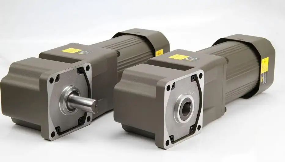
Stage count compounds losses. A two-stage gearbox with 95% efficiency per stage has an overall efficiency of 0.95 × 0.95 = 90.25%, not 95%. A three-stage version drops to approximately 85.7%. The more stages needed to achieve a high ratio, the lower the overall efficiency — and the greater the gap between the calculated and actual output torque.
Speed and load affect efficiency. Research on DC gearmotor efficiency modeling decomposes gear losses into two components: a speed-independent component (coulomb friction — the baseline drag that stays roughly constant regardless of speed, approximated from the catalog efficiency value) and a speed-dependent component (viscous friction — additional drag that grows as the gears spin faster). At very low output speeds, the viscous component decreases, but the coulomb component remains — meaning the actual efficiency at your operating point may differ from the catalog nominal value.
Lubricant and temperature play a role. At low ambient temperatures, lubricant viscosity increases, raising gearbox friction and reducing efficiency. This effect is particularly relevant for outdoor or cold-storage equipment where the motor may start at sub-zero temperatures.
Practical Guidance
When calculating output torque, use an efficiency range rather than a single value. If the catalog states “efficiency: 80%,” calculate with both 75% and 80% to understand the sensitivity. For multi-stage gearboxes, multiply per-stage efficiency to estimate overall efficiency rather than using a single overall figure.
The Gearbox Rated Torque Limit: Where Calculations Meet Physical Constraints
Even if the calculated output torque looks adequate for the application, the gearbox itself has a maximum torque it can transmit. This limit — called the rated output torque or gearbox torque capacity — is determined by:
- Gear tooth strength: The teeth must withstand the bending and contact stresses at the operating load.
- Bearing capacity: The output shaft bearings must support the radial and axial loads imposed by the driven component.
- Shaft dimensions: The output shaft diameter and keyway must transmit the torque without shearing.
If your calculated output torque exceeds the gearbox rated torque, the solution is not to use a more powerful motor — it is to use a larger gearbox frame. A larger frame has bigger gears, larger bearings, and a stronger output shaft, all of which raise the torque capacity.
A Common Scenario
An engineer calculates that a 100:1 ratio with a 0.3 N·m motor gives 24 N·m output torque (at 80% efficiency). The calculation is correct. But the gearbox selected for this ratio has a rated output torque of only 15 N·m. The motor will produce the calculated torque only briefly — until the gearbox fails.
This is why every ratio calculation must end with a check against the gearbox catalog rating. The motor torque × ratio × efficiency gives the theoretical output; the gearbox rated torque gives the physical limit. The lower of the two governs.
Motor Rated Torque vs. Stall Torque: A Critical Distinction
DC motor datasheets typically list several torque values:
| Parameter | Definition | Role in Sizing |
| Rated (continuous) torque | The torque the motor can deliver continuously without exceeding its thermal limit | Primary sizing basis |
| Stall torque | The maximum torque at zero speed (motor shaft held stationary) | Must not be used as a continuous operating point |
| Peak / starting torque | The momentary torque available during acceleration | Must stay within gearbox peak capacity |
Stall torque is not a working torque. A motor’s stall torque might be 3–5 times its rated torque, but the motor cannot sustain this — the current draw at stall is the highest the motor will ever pull, and the resulting heat will damage the windings within seconds to minutes.
When calculating the gear ratio, always use the rated torque as the motor input value. Reserve the stall or peak torque for a separate startup check: verify that the peak torque during acceleration (including the gear ratio multiplication) does not exceed the gearbox’s allowable peak torque.
Startup and Impact Loads: Why Safety Margin Matters
The running torque may be steady at 5 N·m, but what happens when the conveyor starts with a full load? Or when the indexing mechanism hits a mechanical stop?
Startup Torque
When a motor starts under load, it must overcome static friction (typically higher than dynamic friction), the inertia of the load, and the running torque. Startup torque can be substantially higher than steady running torque, depending on load inertia, static friction, acceleration time and whether the mechanism starts under load.
Shock Loads
Impact loads — from crushers, presses, or mechanisms that hit mechanical stops — can produce momentary torque spikes well above the rated value. These spikes may not be sustained, but they stress gear teeth, bearings, and shafts.
Applying Safety Margin
Because startup and shock loads vary by application, there is no universal safety margin that applies to all cases. The appropriate approach depends on the load characteristics:
| Load Type | Typical Consideration |
| Smooth, constant load (fan, centrifugal pump) | Minimal margin needed; startup torque is close to running torque |
| Conveyor with product load | Account for startup under full load; margin depends on whether load can be emptied during startup |
| Indexing mechanism with stops | Shock load at each stop; check gearbox peak torque rating |
| Crusher or press | High impact loads; may require a gearbox rated well above the calculated running torque |
Rather than applying a blanket multiplier, the recommended approach follows three checks:
- Check running torque vs. rated: Calculate the running torque using rated motor torque, ratio, and efficiency. Confirm it is within the gearbox catalog rating.
- Check peak torque vs. allowable peak: Estimate the startup/peak torque based on the load type. Compare the calculated peak torque with the manufacturer’s allowable peak/emergency torque rating for the specific gearbox.
- Check thermal capacity vs. duty pattern: If the peak exceeds the gearbox limit, select a larger frame or a different gear type with higher peak capacity. If the duty cycle involves frequent starts, verify that the motor’s thermal capacity can handle the repeated startup current surges.
A simple way to remember this: check three limits — running torque vs. rated, peak torque vs. allowable peak, thermal capacity vs. duty pattern. If all three pass, the selection is sound. If any one fails, the drive needs a larger frame, a different ratio, or a different gear type.
A Complete Calculation Example
Let us work through a hypothetical example to illustrate the full process. Note: the motor and gearbox values below are illustrative — actual values must come from a supplier’s selection tables or engineering data.
Application: A packaging indexing mechanism
- Target output speed: 40 rpm
- Running torque (measured or calculated from load): 6 N·m
- Startup torque (estimated): 12 N·m (2× running, due to static friction and load inertia)
- Supply voltage: 24V DC
- Starts per hour: 20
Step 1: Calculate the ratio
Using a motor rated at 2,400 rpm: Ratio = 2,400 ÷ 40 = 60:1
Step 2: Estimate output torque
Motor rated torque: 0.25 N·m (from motor datasheet) Estimated gearbox efficiency for a 2-stage planetary: ~85% (0.90 × 0.94 ≈ 0.85) Output torque = 0.25 × 60 × 0.85 = 12.75 N·m
This exceeds the 6 N·m running torque requirement with margin.
Step 3: Check gearbox rated torque
The gearbox selected for a 60:1 ratio has a rated output torque of 15 N·m. The calculated 12.75 N·m is within the rating.
Step 4: Check peak torque
Startup torque at output: 12 N·m (running) × 2 = 24 N·m peak (illustrative — actual startup torque depends on load inertia and acceleration profile) If the gearbox allowable peak is 30 N·m (from the manufacturer’s data for this model), the peak of 24 N·m is within limits.
Step 5: Verify thermal suitability
20 starts per hour with 12 N·m peak each — the intermittent duty profile must be checked against the motor’s thermal capacity. The average torque is closer to the running value, but the repeated startup current draws need verification. This step requires supplier data: send the duty pattern (minutes on/off, starts per hour, ambient temperature) and ask for thermal confirmation against the motor’s thermal time constant and insulation class.
This example shows how the simple ratio formula (Step 1) is only the beginning. Steps 2–5 are where most selection errors are caught — or missed.
Five Common Calculation Errors — and How to Avoid Them
| # | Error | Consequence | Correct Approach |
| 1 | Using stall torque as the motor input value | Motor overheats; stall torque is a momentary value, not sustainable | Always use rated (continuous) torque for the ratio calculation |
| 2 | Applying a single fixed efficiency (e.g., “90%”) | Overestimates output torque, especially with multi-stage or worm gear sets | Use efficiency ranges based on gear type and stage count; multiply per-stage efficiency for multi-stage gearboxes |
| 3 | Ignoring the gearbox rated torque limit | Theoretical torque exceeds what the gearbox can physically transmit, leading to gear or bearing failure | Always check calculated output torque against the gearbox catalog rating |
| 4 | Not accounting for startup or shock loads | Gearbox peak capacity exceeded during acceleration or impact, causing premature failure | Estimate peak torque and verify against gearbox allowable peak |
| 5 | Confusing motor rated torque with output torque | Forgets to multiply by ratio and efficiency, resulting in a drastically undersized drive | Output torque = motor torque × ratio × efficiency — not motor torque alone |
Unit Conversion Reference
Torque values in DC motor specifications may appear in N·m, kgf·cm, or oz·in depending on the supplier and product origin. The most common conversions:
- 1 N·m = 10.197 kgf·cm
- 1 kgf·cm = 0.0981 N·m
- 1 N·m = 141.61 oz·in (commonly used in North American product catalogs)
When sending specifications to a supplier, confirm which unit system they use for selection tables. Mixing units is one of the most common sources of sizing errors in cross-border procurement.
Next Step: Verify Your Ratio and Torque With a Supplier
The calculation process above gives you a ratio, an estimated output torque, and a peak torque value. The next step is to verify these against a supplier’s actual product range — because the available ratios, frame sizes, and torque ratings may not align exactly with your calculated values.
If you have your motor rated speed and target output speed ready, send both values — a supplier can quickly confirm the available ratio range and whether a standard or custom ratio is needed. If your load involves startup impacts, include the startup condition, peak load, and starts per hour so the torque check can account for peak conditions, not just running torque.
For applications where the torque is not yet known, sending the load description (weight, radius, mechanism type, speed) allows the supplier to assist with estimating the required torque before confirming the ratio and frame size combination.
Share on Social:


Contact Us
In This Article
Right Angle Geared Motor: Matching Electrical Supply, Variable Speed and Braking
Oct 26, 2026
Planning a Bevel Reducer Installation: Turn Shaft Requirements Into a Practical Drive Layout
Oct 26, 2026
Choosing an Overhead Crane Gearbox by Its Hoisting or Travel Function
Oct 26, 2026
Replacing an Industrial Worm Gearbox: What to Keep and What to Reassess
Oct 25, 2026