


 Home /
 Welding Rotator Gearbox: How It Supports Stable and Controlled Turning

Metallurgy and Heat Treatment for Durable Twin Shaft Paddle Mixer Gearbox Gears
Jul 16, 2026

Torque Distribution in a Double-Shaft Paddle Mixer Special Reducer
Jul 15, 2026

Backlash Control in Special Reducer for Welding Turning Rolls
Jul 14, 2026

Welding Rotator Gearbox: How It Supports Stable and Controlled Turning
Jul 13, 2026
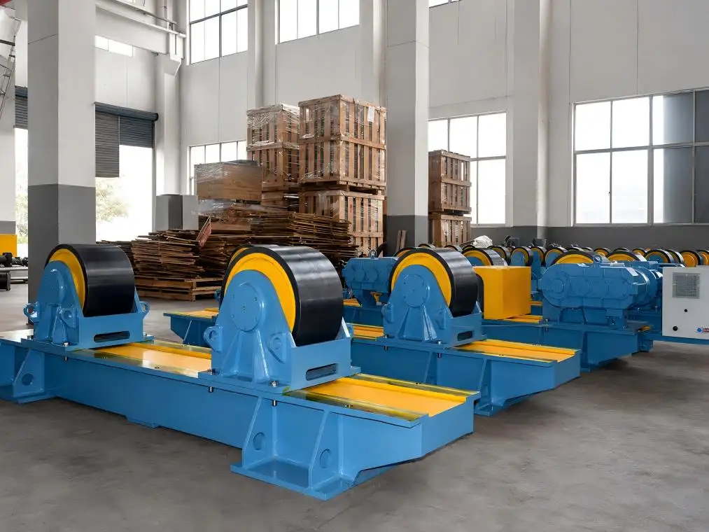
Welding rotators are designed to assist in the alignment and welding of cylindrical components, including pipes, tanks, pressure vessels, and similar fabrications. Rotators have direct contact with workpiece rollers. However, thanks to a modular design, the movement of the rollers in the rotators is a function of the gearbox, motor, shafts, controls, frame, and alignment.
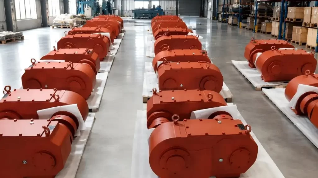
A welding rotator gearbox transforms the high-speed motor input to a low-speed, high-torque output to suit the requirements of welding rotators. It also plays a role in the consistent transmission of torque and sustains a predictable workpiece movement throughout the welding cycle.
From Mingye's manufacturing perspective, gearbox selection should begin with the rotator layout and operating conditions rather than nominal size alone.
Welding Rotator Gearboxes Explained
The drive pathway of welding rotators can be described in five stages:
1. Motor input: This stage of the drive pathway begins at the motor input.
2. Speed reduction: The drive's gearbox reduces the speed of the drive to allow higher control of the rotation speed of the vessel.
3. Torque Transmission: A geartrain supplies and transmits the required torque of the drive.
4. Roller Drive: Drive shafts or couplings cause the driven rollers to rotate.
5. Workpiece rotation: The workpiece will rotate about its axis as a result of the frictional drag between the powered rollers and the vessel.
When the welding head is in a fixed position, rotating the vessel in relation to the welding head will result in variable travel speed and poor-quality welds. The stability of the system is aided by the gearbox; however, alignment, controls, the condition of the rollers, the workpiece, and the load distribution are also important factors.
Why Low-Speed Stability Matters
Welding rotators normally require controlled low-speed output. The setting depends on workpiece diameter and the surface travel speed required by the welding process.
•Steady Engagement: Consistent engagement of components reduces abrupt changes in rotation.
•Controlled Starting: Proper incremental reductions help eliminate harshness when a heavy vessel is started in rotation.
•Usable Torque: A higher output torque will help in the overcoming of inertia and rolling resistance.
•Long Cycle Operation: Proper sizing allows for long periods of operation.
•Repeatable Positioning: Rotation in a predictable manner will help in maintaining the joint steady with respect to the welding head.
A gearbox cannot correct for a large degree of misalignment or insufficient support of the workpiece. Reliable movement depends on the complete welding rotator system.
Gearbox Features and Practical Value
| Technical Factor | Role in the Welding Rotator | Practical Value |
| Reduction Ratio | Determines the relationship between motor speed and roller speed | Supports an appropriate workpiece surface speed |
| Output Torque | Provides the force required to rotate the workpiece | Helps turn heavier or larger vessels |
| Gear Material and Heat Treatment | Influences surface hardness, core strength, and wear resistance | Supports repeated industrial loading |
| Gear Accuracy | Limits tooth-profile and tooth-flank deviations | Contributes to smoother torque transmission |
| Shaft and Mounting Layout | Connects the gearbox to the rollers and machine structure | Accommodates different equipment layouts |
| Lubrication and Sealing | Protects gears, bearings, and internal surfaces | Helps control wear and prevent contamination |
Mingye's JA, JB, and JC series are dedicated reducers for welding rotators. Mingye specifies high-strength alloy steel for major parts and low-carbon alloy steel gears treated by carburizing and quenching.
The stated gear-surface hardness is 58–62 HRC, a range consistent with published references for carburized gear steels. Mingye also states Grade 6 gear accuracy. Because gear-accuracy grades depend on the governing standard and inspection method, the applicable standard should be confirmed in project documentation.
Matching the Gearbox to the Rotator Type
The gearbox should be matched to different types of welding rotators.
| Rotator Type | Gearbox Selection Consideration |
| Bolt-Adjustable Rotator | Shaft position and transmission layout should match the fixed roller-spacing positions |
| Self-Aligning Rotator | Transmission should remain stable as roller contact angles change |
| Lead-Screw Adjustable Rotator | Output direction and shaft alignment should accommodate movable roller spacing |
| Fit-Up Rotator | Low-speed control should support joint alignment, positioning, and assembly work |
A gearbox that fits mechanically may still be unsuitable if its ratio, torque, duty cycle, or control method does not match the application.
Information Required Prior to Selection
The design selection of gearboxes for welding rotators should incorporate application data rather than solely the weight of the workpiece.
•Workpiece Specifications: Provide, as applicable, the diameter, length, weight, eccentricity, etc.
•Speed Requirement: Specify the surface speed of the workpiece or the speed of the rollers.
•Duty Cycle: Provide details on the work cycle—how frequent is the operation: continuous, frequent, or intermittent?
•Rotator structure: Adjustment method and workpiece support arrangement.
•Drive layout: Provide the characteristics of the motor, position of the shaft, design of the mounting space, type of coupling, and direction of output.
•Site conditions: Provide the temperature, dust, and humidity range and state of maintenance, including accessibility.
•Replacement data: Provide nameplates, drawings, photos, and evidence of the operation.
This information allows us to determine whether the gearbox can provide the assumed output without excessive and inappropriate offset of the transmission.
Mingye's Application-Based Approach
At Mingye, we treat the reducer as one part of the entire drive system for the welding rotator. Technical discussions focus on equipment layout, workpiece range, transmission arrangement, and operating method.
•Dedicated design: JB configurations are developed for welding-rotator applications rather than positioned only as general-purpose reducers.
•Integration support: Position, alignment, and direction of output can be checked against the design of the machine.
•Project flexibility: Drawings and operational data can be used to discuss new, original equipment manufacturer, replacement, and upgrade needs.
•Material planning: Alloy-steel components with gear surfaces carburized and treated for special cases can provide controlled transmission considering industrial running conditions.
•Technical review: Before proposing a configuration, we validate the application information in detail.
With this application-oriented approach, users can assess the gearbox against real operating conditions, instead of just model names or rated capacity.
Uninterrupted Rotation Maintenance
The gearbox will be serviced along with the other components of the welding rotators.
•Lubrication: Refer to the gearbox service instructions for the evaluation of the oil. This will assist in determining the oil's condition and the oil change frequency.
•Alignment: Inspect the position of the motor, gearbox, shafts, and powered rollers for correctness.
•Temperature: Overheating can be caused by one or a combination of the following: overload, insufficient lubrication, worn bearings, or misalignment.
•Noise and Vibration: An abnormal condition of a gearbox can be caused by looseness or wear or can be the result of a gearing problem.
•Sealing: Lubricating oil loss and contamination of the gearbox occur due to leakage. The issue must be corrected.
Closing Words
A properly matched gearbox helps welding rotators deliver controlled low-speed movement. Dependable performance, however, comes from a coordinated system design. Reduction ratio, output torque, gear treatment, alignment, controls, roller condition, and workpiece support should therefore be evaluated together.
Please provide Mingye with the type of rotator, the type of workpiece, the speed of operation, motor information, and drawings. In the regular course of our activities, we evaluate an application and design the appropriate reducer for an equipment project (i.e., new installation, replacement, or upgrade).
FAQs
Q1: What is a welding rotator gearbox?
The welding rotator gearbox is a speed reduction with an increase in torque. This allows for the controlled rotation of the workpiece.
Q2: For what purpose do Welding Rotators require low-speed outputs?
Low-speed outputs are necessary for welding travel to maintain consistent positioning of the joints.
Q3: Which Welding Rotators are compatible with this gearbox?
This gearbox can be used with bolt-adjustable, self-aligning, lead-screw, and fit-up rotators.
Q4: Can you modify the gearbox?
Yes, modifications are available for customization based on load and speed in addition to the layout and shaft position.
Q5: Is this gearbox appropriate for heavy vessels?
This gearbox can be used for heavy vessels depending on the weight and diameter of the vessels, as well as the distribution of the load and the torque requirement.
Share on Social:


Contact Us
In This Article
Metallurgy and Heat Treatment for Durable Twin Shaft Paddle Mixer Gearbox Gears
Jul 16, 2026
Torque Distribution in a Double-Shaft Paddle Mixer Special Reducer
Jul 15, 2026
Backlash Control in Special Reducer for Welding Turning Rolls
Jul 14, 2026
Welding Rotator Gearbox: How It Supports Stable and Controlled Turning
Jul 13, 2026