


 Home /
 Decoding "Low Speed, High Torque": How a Welding Roller Bed Achieves Smooth Rotation for Vessel Welding?
Gear Motor Factory With Modular Design For Easy System Integration
Jun 19, 2026
From Input to Output: A Step-by-Step Look at the Ball Mill Gearbox Power Transmission Path
Jun 18, 2026
Vibration and Noise Control: How a Cycloidal Reducer Achieves Smooth Operation
Jun 17, 2026
How a Planetary Gearbox Achieves High Load Capacity – Dual Bearing & Needle Roller Secrets
Jun 16, 2026
When a large tank or pipe rotates under a welding torch, even a tiny jerk or speed variation can ruin the seam. This is why the drive system of a Welding Roller Bed must solve a fundamental mechanical paradox: turn very slowly, yet with enormous force. The answer lies in a concept called "low speed, high torque" – and a dedicated gearbox designed specifically for controlled rotation.
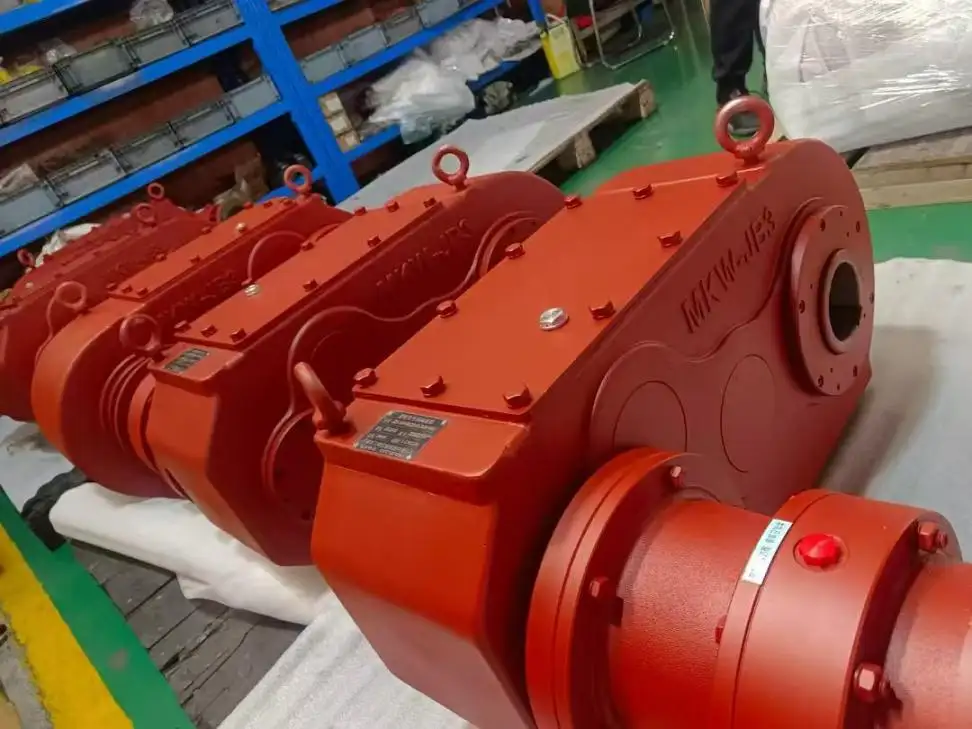
Why Smooth Rotation Matters in Cylindrical Fabrication
A Welding Roller Bed supports and rotates heavy cylindrical workpieces such as pressure vessels, storage tanks, and pipes. During automatic welding, the workpiece must turn at a precisely controlled linear speed. If rotation is uneven:
•The welding arc may drift off the joint.
•Depth of penetration starts to vary.
•Weaknesses such as porosity and undercuts may also develop.
•Rework rates are greatly affected.
To eliminate these issues the drive system will need to deliver high torque at very low revolutions per minute (RPM) with close to zero motion variation. This is the exact application for a welding rotator gearbox.
What Is Considered "Low Speed, High Torque"?
To explain this concept simply, torque refers to a twisting force. Think of it as how hard you would have to push to get a quite heavy object to start turning. Speed refers to how quickly the object can turn.
•Low speed (generally between 0.1 – 2 RPM): Lets the weld bead build up as it should.
•High torque: Is required to overcome inertia of a heavy and/or out of balance workpiece.
The majority of standard industrial reducers usually emphasize high speed operation. But a Welding Roller Bed requires a gearbox that deliberately reduces input speed while multiplying torque, without introducing vibration or irregular rotation. This is not a generic reducer; it is an application-specific solution.
The Hidden Problem: Stick-Slip and Load Variation
When a large vessel begins to rotate, static friction between the roller and the workpiece resists motion. Once movement starts, dynamic friction takes over. Without proper torque management, the system can "jump" – a phenomenon known as stick-slip. This causes:
•Intermittent rotation (crawling).
•Uneven weld bead formation.
•Excessive wear on rollers and drive components.
Moreover, as the welding progresses, the effective weight distribution may shift (e.g., when adding a heavy end cap). The drive must respond without sudden speed changes. A welding roller bed uses a gear system which solves the issue of inconsistent speeds of rotation over changing conditions of the load.
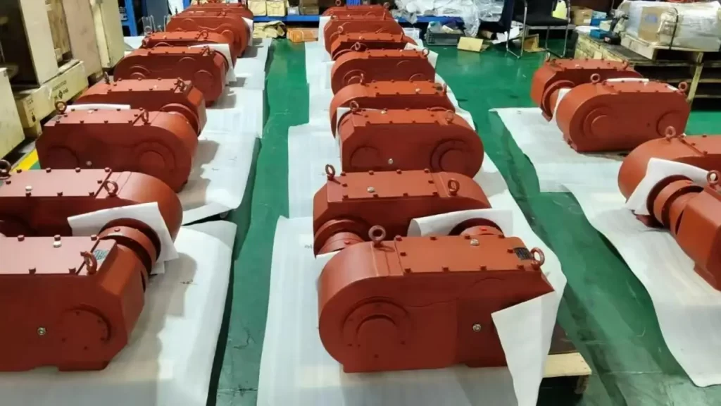
How a Specialised Welding Rotator Gearbox Achieves Low Speed, High Torque
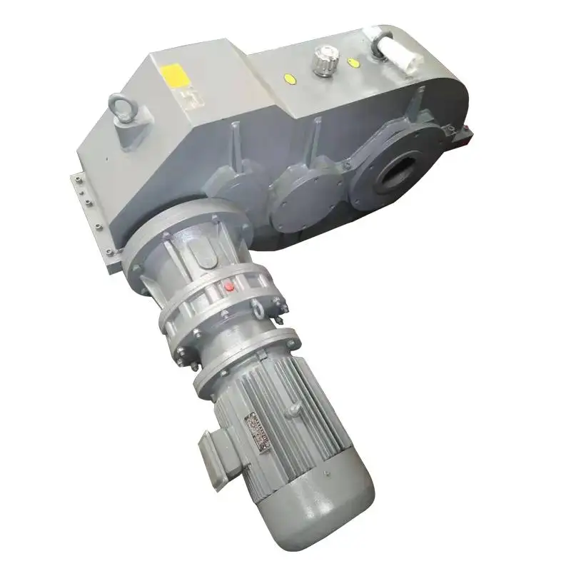
Mingye Machinery has a special reducer line (JA/JB/JC) for welding rotator systems. This is a complete system designed from scratch and is not a modified general system like most of the welding rotators. Here is how it achieves what it does:
Gear System for Controllable Rotation and Load
•Consistent speed through gears: This gear assemblies purpose is to reduce the input from the motor (which may be high) to a low output at a constant speed (without spikes).
•Equally distributed torque: The rotation of the system distributes the torque over a number of gear teeth (and shafts).
•Rotator Wheel Fit Alignment: The system is designed to integrate perfectly the the rotator roller wheel support.
•Constant output through changing loads: The gear system is designed to mesh without backlash therefore the system maintains motion output at all times regardless of the load.
Material and Manufacturing Precision
•In a high carbon alloy steel: The housing and components of the system are designed to retain their shape and resist deformation.
•Low carbon, alloy steel gears that have been carburised and quenched: This tempered the outside of the gear making it hard and wear resistant, while keeping the inside tough and able to absorb shocks.
•Gear accuracy attains Grade 6 (ISO 1328): Grade 6 accuracy denotes a sufficient degree of accuracy of the tooth trace profiles such that runout deviations and pitch errors will be so small as to have no significant effect on the smoothness of meshing engagement. This precision directly reduces rotation irregularity.
Application-Specific Design Philosophy
•Developed for welding rotator systems, not generic reducers: Every design choice – from shaft diameter to housing stiffness – is optimized for low-speed, high-torque welding duty cycles.
•Heavy-duty structure for industrial workshops: The gearbox withstands continuous operation, dust, and temperature variations without losing performance.
•Flexible integration with different rotator layouts: Shaft alignment, mounting position, and output direction can be matched to bolt-adjustable, self-aligning, or lead-screw-adjustable rotator designs.
Why a Generic Reducer Is Insufficient for a Welding Roller Bed
Many users consider using a standard industrial gearbox to save cost. Typically, a generic reducer:
•Has gear profiles optimized for greater speeds making their lubrication insufficient at lower RPM (especially at low RPM).
•Utilizes softer materials (e.g., 40–50 HRC) with high wear rates under high repeating torques.
•Has insufficient backlash control to eliminate stick-slip at the starting condition.
On the other hand, a Welding Roller Bed gearbox (JA/JB/JC series) is designed for low speed control. Instead of chasing high RPM, it emphasizes uniform angular velocity – the key to welding accuracy.
Integration Flexibility: Matching Different Equipment Designs
Every fabrication workshop has unique layouts. Some use self-aligning rotators to accommodate out-of-round vessels; others use lead-screw adjustable types for varying diameters. Mingye Machinery's approach allows:
•Customization discussions based on rotator structure: Whether your system has fixed or adjustable wheel stations, the gearbox configuration can be adapted.
•Support for new equipment or replacement projects: If an older Welding Roller Bed is being upgraded, we can assess the existing mounting dimensions and power parameters.
•OEM Supply Focus: For those who manufacture complete welding lines, the gearbox can become an integrated core component and be developed jointly according to the workpieces and methods of operation.
Practical Advantages in Heavy Fabrication
Incorporating a dedicated low-speed, high-torque gearbox to a Welding Roller Bed will deliver the following benefits:
•Weld quality that is uniform across the entire circumference: With no differing of speeds, the Heat Input and Penetration will also be uniform.
•Less mechanical strain on rollers and bearings: The gradual transfer of Torque load will prevent premature failure.
•The capacity to operate on large vessels and with off-center loads: The gear train will maintain control of the motion, even when the workpiece is unbalanced.
•Lower operator intervention: Automated welding proceeds without need for manual speed correction.
How to Choose the Right Gearbox for Your Welding Roller Bed
Before selecting a welding rotator gearbox, gather the following information – it will make technical discussions more efficient:
•Machine type and rotator structure: Is it bolt-adjustable, self-aligning, or lead-screw adjustable?
•Workpiece dimensions and capacity range: Outer diameter, length, and maximum weight.
•Operating method: Manual, semi-automatic, or fully automated welding line.
•Drawings or reference data: Existing mounting hole patterns, shaft dimensions, or previous gearbox models.
With this data, a supplier like Mingye Machinery can propose a configuration – not a rigid standard parameter – that truly matches your Welding Roller Bed application.
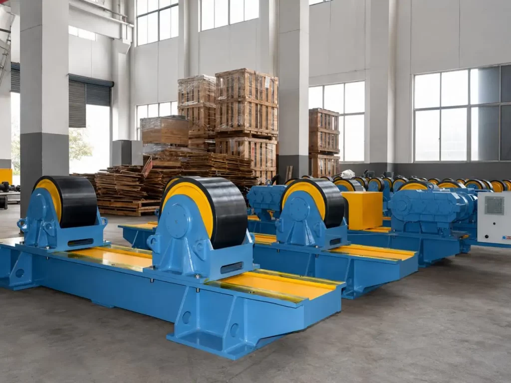
Conclusion: Low Speed, High Torque Is a System Engineering Achievement
Achieving smooth rotation for vessel welding is not about a single powerful motor. It is about how torque is reduced, multiplied, and delivered through a gearbox designed for the job. A Welding Roller Bed that integrates a dedicated welding rotator gearbox – with case-hardened Grade-6 gears, application-specific geometry, and flexible integration – will deliver years of stable, accurate rotation. Whether you are building a new fabrication line or replacing an underperforming drive, focusing on low-speed, high-torque design is the most direct path to better welds and lower rework costs.
Need a solution matched to your exact rotator structure and workpiece range?
�� Get Free Quote – Share your machine type, drawings, or capacity requirements for a configuration discussion.
FAQs
Q1: Why does a welding roller bed need low speed rather than high speed?
A: Welding requires a slow, steady rotation (typically 0.1–2 RPM) to maintain consistent heat input and bead formation; high speed would ruin weld quality.
Q2: What is the meaning of high torque regarding a welding roller bed?
A: High torque refers to the bed's capability to rotate very large and very heavy workpieces as well as those workpieces that have an uneven weight distribution.
Q3: Is it possible to install a standard industrial gearbox on my welding roller bed?
A: Not recommended - standard reducers usually don't have enough lubrication for low-speed operation, have low gear hardness and exhibit excessive backlash, resulting in poor and uneven rotation.
Q4: How does gear hardness (58-62 HRC) affect roller bed performance?
A: A harder gear surface will not wear or pit over time, and will maintain long term accurate rotation, even for heavy torque.
Q5: Does the welding roller bed gearbox need customization?
A: Often yes – configuration depends on rotator structure (bolt-adjustable, self-aligning, etc.), workpiece dimensions, and mounting layout.
Share on Social:


Contact Us
Gear Motor Factory With Modular Design For Easy System Integration
Jun 19, 2026
From Input to Output: A Step-by-Step Look at the Ball Mill Gearbox Power Transmission Path
Jun 18, 2026
Vibration and Noise Control: How a Cycloidal Reducer Achieves Smooth Operation
Jun 17, 2026
How a Planetary Gearbox Achieves High Load Capacity – Dual Bearing & Needle Roller Secrets
Jun 16, 2026