


 Home /
Single-Screw Extruder Gearboxes: Why Axial Thrust Needs Its Own Load Check
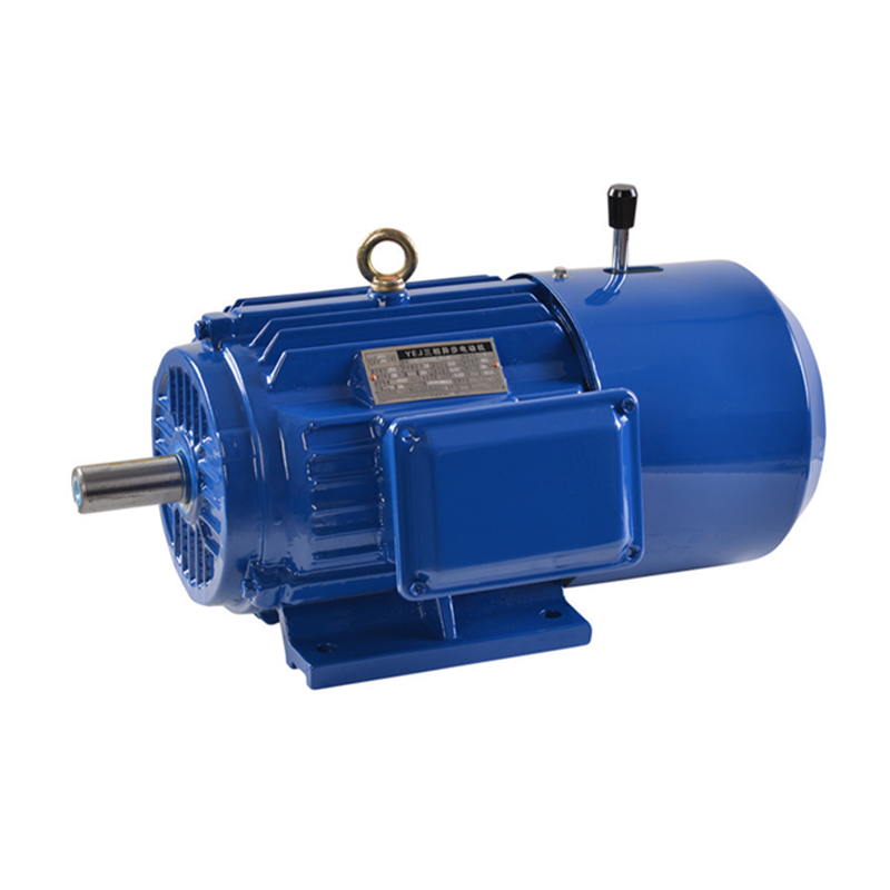
Vertical-Axis Drives After Power Loss: Which Holding and Brake Data Must OEMs Verify?
Oct 14, 2026
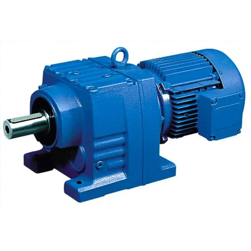
Indexing Packaging Machines: Calculating Acceleration Torque From a Motion Profile
Oct 14, 2026

Changing an NMRV Worm Gearbox Ratio: Can You Keep the Existing Motor?
Oct 14, 2026
How to Check Overhung Load When a Chain Sprocket Is Moved Along a Gearbox Output Shaft
Oct 14, 2026
An extruder gearbox review often starts with output torque and speed. The required operating points appear to fit the gearbox ratings, and the numbers look settled. But the screw also pushes back along its own axis. That axial reaction is a different load from the torque the shaft carries, and it can remain unchecked even when the rotational ratings look suitable.
Axial thrust is not a footnote to the torque rating. It is a separate load with its own path, limits, and bearing arrangement. Sizing a gearbox on torque alone leaves the thrust side of the application unchecked. Here is how to treat it as its own load case.
Why the Same Torque Does Not Mean the Same Thrust Capability
Two extruders can demand the same output torque and impose very different axial thrust. The torque comes from turning the screw against the polymer; the thrust comes from the screw pushing the melt forward and the die resisting it. Process changes can affect both, but they are not the same quantity, and torque alone does not establish the thrust.
That is why a torque rating does not answer the thrust question. A gearbox rated for a given output torque may carry a thrust bearing sized for one class of screw and process, and the next application, same torque, same speed, same screw diameter, can load the thrust path far harder through higher head pressure or a different die. The load check has to happen on the thrust side as its own item, using the process data, not the torque number.
How a Screw Generates Axial Force and How It Differs from Torque
Inside a single-screw extruder, the rotating screw drags polymer forward against the resistance of the die and downstream equipment. That resistance acts back along the screw axis as an axial force. The magnitude depends on screw geometry, the polymer, the head pressure, and the process temperatures, not on the motor's torque alone.
Because the axial force runs along the shaft while the torque runs around it, they load the drive train in different ways. The shafts transmit torque in torsion, while gear-mesh forces are reacted by their bearings. Helical gearing can create its own axial forces as well. The screw's process thrust must be traced separately to the bearing arrangement intended to react it. The two loads demand different checks, and a design that is sound on the torque side can be weak on the thrust side, or the reverse.
Follow the Force Path from Screw to Frame
The practical way to check thrust is to trace where the force goes, from the screw to the machine frame.
A useful starting sketch is screw → axial reaction interface → thrust bearing or thrust support → supporting housing and mounting structure → machine frame or base. Confirm that path on the assembly drawing. An integrated support may react through the gearbox assembly; an independently mounted thrust unit can close the force path through its own support. A key or spline that transmits torque does not, by itself, establish axial retention. Check the shoulder, collar, coupling, or other interface that actually transfers the thrust. Once the path is written down, the question becomes concrete: which component takes the thrust, and what is its rated capability?
Published manufacturer documentation treats this as a specific selection item. The Rossi GX technical catalog, sections 2 and 6, describes an extruder support and checks thrust-bearing life separately from gearbox torque selection. The Bonfiglioli HDPE leaflet likewise selects the thrust bearing according to extrusion forces. These are examples of the engineering distinction; their bearing tables and ratings do not establish the capability of a Mingye configuration.
Decide Whether Thrust Is Integrated or Carried Separately
Because the thrust bearing can sit at the output of the gearbox or in its own housing, the OEM has a real design decision to make, and the default should not be that the gearbox's ordinary output bearings absorb the full screw thrust.
Where thrust support is integrated into the gearbox assembly, a specified output-end bearing arrangement reacts the screw's axial force. Where thrust is carried separately, a dedicated thrust unit takes that force, and the torque connection must be arranged so it does not unintentionally pass the same thrust into the gearbox. A separate housing alone does not prove that the gearbox is isolated from the axial load; mounting and retention details decide the path. Compare the arrangements against the actual load, alignment, available space, and support structure.
Neither arrangement is automatically better. The point is that the decision has to be made deliberately, against the documented design thrust and duty of the process, and not left to whichever bearings happen to be in the gearbox. If the selected configuration has no confirmed permissible screw thrust, its torque rating is not a substitute for that missing approval.
What the OEM Needs to Collect for a Thrust Review
A thrust check is only as good as the inputs. Collect these before the review:
- Screw geometry: diameter, length, and channel design.
- Process data: head or die pressure, melt temperature, throughput, and the polymer.
- Operating envelope: speed range, temperature range, and the load spectrum, including startup and upset conditions.
- Configuration drawing or sketch: how the screw, connection, thrust element, and frame are arranged.
- Axial load magnitude, direction, peaks, and duty from the extruder or process designer, together with the required bearing life.
- Bearing arrangement, lubrication and cooling conditions, and the manufacturer's applicable axial-load and thermal limits.
- For a replacement, the existing arrangement and any signs of thrust-related wear.
With these in hand, the thrust path can be checked end to end: what the process generates, what each element can carry, and where the margin sits.
Gearbox Thrust Review Table
| Review item | What to establish | Typical source | Owner |
|---|---|---|---|
| Screw geometry | Diameter, length, channel design | Extruder drawing | Process |
| Head/die pressure | Design and upset values | Process data | Process |
| Polymer and temperatures | Grade, melt and barrel temperatures | Process data | Process |
| Thrust load | Axial force, direction, peaks, duty and design margin | Extruder or process designer | Process |
| Torque load | Required torque and speed over the duty cycle | Extruder designer; compare with gearbox ratings | Mechanical |
| Thrust path | Which element absorbs the axial force | Configuration drawing | Mechanical |
| Thrust support | Permissible load and calculated life for the actual speed, duty and conditions | Supplier data and load review | Mechanical |
| Screw and shaft interfaces | Torque connection and actual axial retention checked for their respective loads | Assembly drawing and supplier data | Mechanical |
| Integrated vs. separate | Where thrust is taken, by design | Configuration drawing | Engineering |
| Mounting and frame | Structure able to react the axial load | Frame drawing | Engineering |
| Lubrication and cooling | Applicable limits satisfied for the selected bearing and duty | Manufacturer's instructions | Mechanical |
| Final sign-off | All items closed and recorded | Review sheet | Project |
The table does not compute the thrust; it makes sure the thrust is owned by someone, sourced from process data, and checked against rated capability before the screw turns.
FAQ
Is the gearbox output power rating enough to select an extruder gearbox? No. A power or torque rating alone does not establish axial-load capacity. The thrust path, bearing arrangement, and axial retention interfaces all need to be checked against the process thrust. Selecting on power alone can leave the thrust side unverified.
When the process changes, what needs to be rechecked on the gearbox? Reconfirm the thrust load from the new process conditions, since a different polymer, die, or head pressure can change the axial force. Then re-check the bearing and support against their permissible loads and required life, the relevant interfaces for the loads they carry, and the torque side for the new speed and throughput. Do not assume that a previously approved torque duty also approves the new thrust duty.
Next Step
If you are specifying or replacing a single-screw extruder gearbox and want the thrust side checked, send us the screw geometry, the process conditions, and the drive configuration. Ask us to review the thrust path and the available configuration against those inputs; the actual load capability needs to be confirmed for the selected unit. Explore our single-screw extruder gearbox, or contact us to start a configuration review.
Share on Social:


Contact Us
In This Article
Vertical-Axis Drives After Power Loss: Which Holding and Brake Data Must OEMs Verify?
Oct 14, 2026
Indexing Packaging Machines: Calculating Acceleration Torque From a Motion Profile
Oct 14, 2026
Changing an NMRV Worm Gearbox Ratio: Can You Keep the Existing Motor?
Oct 14, 2026
How to Check Overhung Load When a Chain Sprocket Is Moved Along a Gearbox Output Shaft
Oct 14, 2026