


 Home /
Welding Turning Rolls: From Weld Travel Speed to Roller RPM and Gearbox Ratio
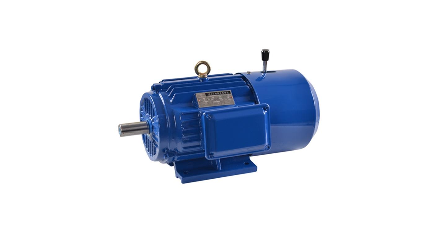
Right Angle Geared Motor: Matching Electrical Supply, Variable Speed and Braking
Oct 26, 2026
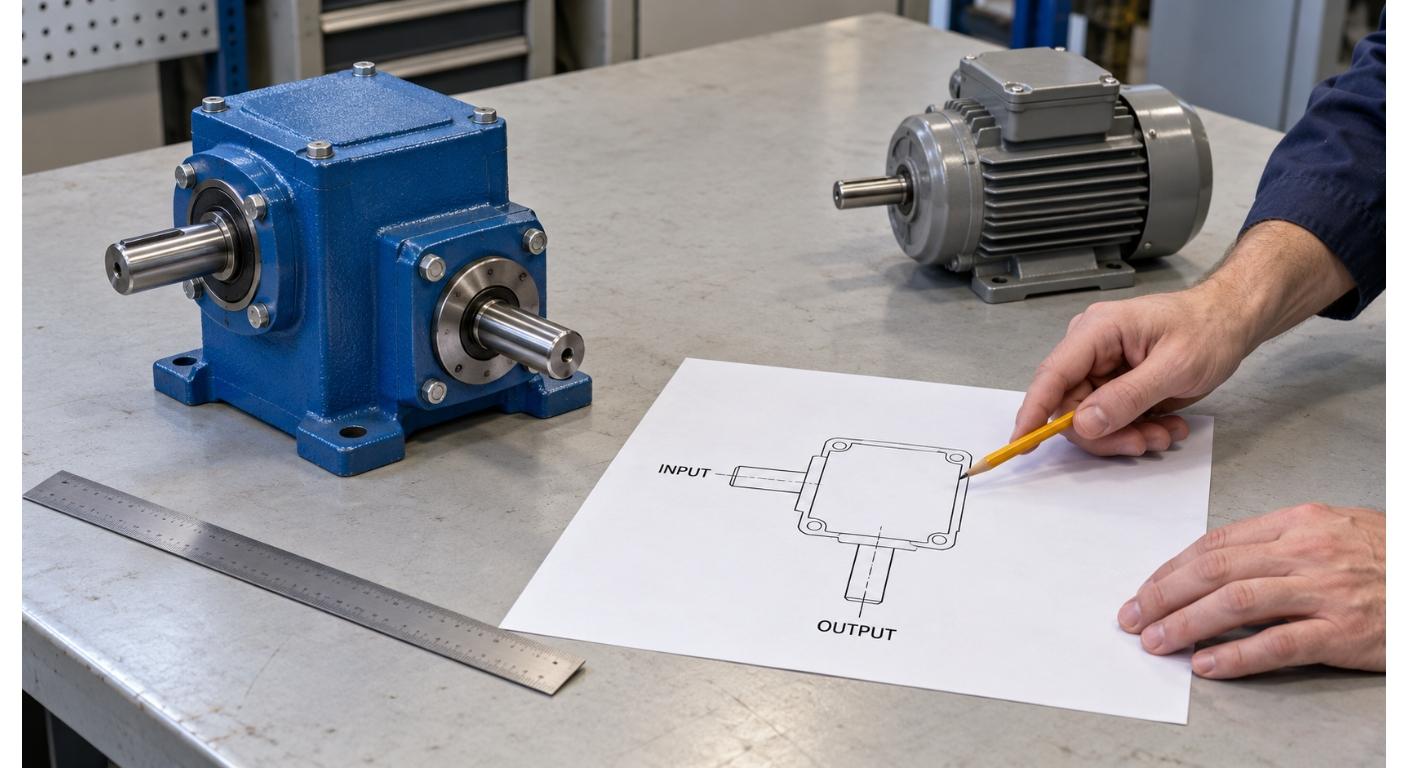
Planning a Bevel Reducer Installation: Turn Shaft Requirements Into a Practical Drive Layout
Oct 26, 2026
Choosing an Overhead Crane Gearbox by Its Hoisting or Travel Function
Oct 26, 2026
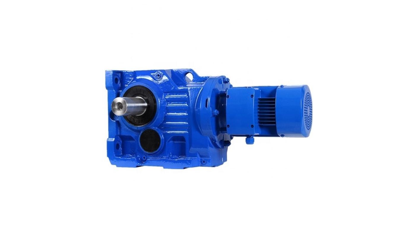
Replacing an Industrial Worm Gearbox: What to Keep and What to Reassess
Oct 25, 2026
The weld procedure calls for a travel speed, often written as a simple number: 600 mm per minute, say, for a given pass. The turning-roll drive, on the other hand, is a motor, a gearbox, and a set of rollers, and its catalog data is written in rpm and ratios. The two speak different languages, and the gap between them is where sizing mistakes are made.
The weld travel speed is a surface speed along the joint. It is not the workpiece rpm, and it is certainly not the gearbox output rpm. Getting from one to the other takes four steps in a fixed sequence. Do them in that sequence and the calculated speeds line up; skip a step or confuse the levels and the roll turns at the wrong speed. Here is the full chain, with a worked example.
Why Weld Travel Speed Is Not the Same as Workpiece RPM
Travel speed is how fast the welding arc moves along the joint. For a circular, concentric weld with a stationary torch, the joint moves because the workpiece rotates, so the travel speed is the surface speed of the joint as it passes the arc. A moving torch or a non-circular joint needs its own relative-motion calculation.
That surface speed depends on two things: how fast the workpiece turns, and how large the joint diameter is. A large-diameter vessel turns slowly to give the same surface speed that a small one reaches at higher rpm. So the same 600 mm/min travel speed means a different workpiece rpm on a 1200 mm shell than on a 600 mm one. Until the diameter is fixed, the travel speed tells you nothing about rpm, which is why the conversion always starts from diameter.
Step 1: Workpiece RPM from Travel Speed and Weld Diameter
For that circular weld path, the relationship between surface speed and rotational speed is:
n_work = v_w / (π × D_w)
where v_w is the weld travel speed and D_w is the diameter of the joint at the weld. Both must be in consistent units, so keep the diameter in millimetres to match a travel speed in mm per minute, and the result comes out in revolutions per minute. Convert m/min to mm/min, or mm/s to mm/min, before using a diameter in millimetres.
Worked example. Take a travel speed of 600 mm/min on a joint diameter of 1200 mm:
n_work = 600 / (π × 1200) = 600 / 3769.9 = 0.15915 rpm
So the workpiece makes about 0.16 of a revolution per minute. That is the number the arc needs, and it is the starting point for everything downstream.
Step 2: Roller RPM from Workpiece RPM and Contact Diameter
The workpiece does not turn by itself; the rollers turn it by friction at the point of contact. For circular contact surfaces concentric with their respective rotation axes and with no slip, the surface speeds match at the contact, so the ratio of rotational speeds is set by the ratio of diameters:
n_roller = n_work × D_contact / D_roller
Here D_contact is the diameter at which the workpiece actually touches the rollers, and D_roller is the effective rolling diameter of the roller under the relevant load. This is the step where a support ring matters. If the workpiece carries a stiffening ring or a support band and it is that band, not the weld-wall surface, that rides on the rollers, then D_contact is the diameter of the band, not the diameter of the joint. Using the weld diameter in its place gives a wrong roller speed. Use the diameter at the actual point of support.
Worked example. For this illustration, assume the rollers contact the 1200 mm shell directly, so D_contact = 1200 mm, and take D_roller = 200 mm. Keeping the unrounded workpiece speed in the calculation:
n_roller = [600 / (π × 1200)] × (1200 / 200) = 0.95493 rpm
The roller turns at roughly 0.95 rpm to drive a workpiece turning at 0.16 rpm. Note the order of magnitude: the roller is faster than the workpiece here, but both are below 1 rpm. This locates the slow end of the drive. The torque needed there still depends on the workpiece and its operating conditions.
Step 3: Gearbox Output from Roller RPM and the Final Drive Ratio
If a final transmission, a chain, sprocket, gear pair, or open gear, sits between the gearbox output and the roller, that final stage changes the speed again. Define the final ratio as:
i_final = n_gearbox_out / n_roller
and solve for the gearbox output:
n_gearbox_out = n_roller × i_final
For direct coupling between the gearbox and roller, i_final = 1. For a simple chain drive, this reduction ratio is the driven roller-sprocket tooth count divided by the gearbox-sprocket tooth count.
Worked example. If the final stage reduces the gearbox output down to the roller by a ratio of 10:1, then the gearbox output is ten times the roller speed:
n_gearbox_out = 0.95493 × 10 = 9.5493 rpm
Keep the levels straight here, because this is the step most often muddled. The gearbox output is 9.55 rpm, the roller is 0.95 rpm, and the workpiece is 0.16 rpm. In this example they are three rotating members at three different speeds. The gearbox output rpm is not the roller rpm and is not the workpiece rpm; it is the speed the gearbox itself delivers, before the final stage takes it down to the roller.
Step 4: Gearbox Ratio from the Actual Motor Speed
With the gearbox output speed known, the overall gearbox ratio follows from the motor speed the drive will actually run at:
i_box = n_motor / n_gearbox_out
Take an illustrative motor speed of 1450 rpm at the working point. Then:
i_box = 1450 / 9.5493 ≈ 152:1
That is the gearbox reduction for this example; the separate final stage supplies another 10:1 reduction. In practice the ratio is chosen from the available gearbox steps close to this figure, then the actual output speed is recomputed from the chosen ratio and the real motor speed, so the travel speed can be confirmed. The chain, in order, looks like this:
motor → gearbox (i_box) → final stage (i_final) → roller → workpiece
Each stage has a defined speed relationship; a direct connection is 1:1. The roller-to-workpiece relationship comes from the contact diameters. Draw the chain before you choose the gearbox, so no level is left undefined.
Check Low-Speed Control and Effective Diameter
Two things deserve a second look once the numbers are in.
The first is low-speed control. A roller below 1 rpm does not by itself mean the motor is below rated speed: in this example, mechanical reduction gives the slow roller speed while the motor runs at the assumed 1450 rpm. Check the actual motor speed range with the selected ratios, then confirm that the drive holds the required travel speed under load. If speed control takes the motor below its normal operating range, check the applicable torque and cooling limits.
Complete selection also needs load and traction checks. Workpiece inertia, eccentricity, rolling resistance and acceleration affect the required torque. Available contact friction, drive-wheel load, thermal duty and the gearbox and final-stage ratings also matter. The speed calculation alone does not establish torque capacity or an allowable workpiece weight.
The second is effective diameter and slip. The no-slip assumption gives the ideal roller speed; in practice the contact can slip if the required traction exceeds the available friction, and any change in the support diameter, a different ring, a different job, changes D_contact and therefore the roller speed for the same travel speed. For a controlled weld, verify the actual joint diameter before each job and confirm the contact diameter that the rollers actually see, then verify the measured weld travel speed against the procedure and adjust the drive as needed. Do not change the specified welding speed simply to suit an available ratio.
Turning-Roll Speed Calculation Table
| Quantity | Symbol | Formula | Worked value |
|---|---|---|---|
| Weld travel speed | v_w | Given | 600 mm/min |
| Weld joint diameter | D_w | Given | 1200 mm |
| Workpiece speed | n_work | v_w / (π × D_w) | 0.15915 rpm |
| Contact diameter | D_contact | Assumed for this example | 1200 mm |
| Roller diameter | D_roller | Given | 200 mm |
| Roller speed | n_roller | n_work × D_contact / D_roller | 0.95493 rpm |
| Final drive ratio | i_final | Given | 10:1 |
| Gearbox output speed | n_gearbox_out | n_roller × i_final | 9.5493 rpm |
| Motor speed (working point) | n_motor | Given (illustrative) | 1450 rpm |
| Gearbox reduction ratio | i_box | n_motor / n_gearbox_out | ≈ 152:1 |
The calculated speeds assume no slip and the stated effective diameters. Keep unrounded values through the calculation, and recompute travel speed after selecting the actual ratios and motor operating point. The approximate 152:1 result is not a verified catalog ratio.
FAQ
Can I size a turning-roll gearbox from the weld travel speed alone? No. Travel speed is a surface speed, and it converts to rpm only after the joint diameter and, further downstream, the contact diameter and final drive ratio are fixed. Those speeds establish the speed requirement; torque, traction, duty cycle and mechanical ratings still have to be checked before selecting the drive.
Why is the gearbox output speed higher than the roller and workpiece speeds? In the worked example, a 10:1 final reduction stage sits between the gearbox and the roller. The gearbox output turns faster, and the final stage reduces that speed down to the slow roller speed. If the gearbox drove the roller directly with no final stage, the gearbox output would equal the roller speed. The presence or absence of that final stage is what sets the level.
Technical References
KOIKE’s TR-R turning-roll specifications list roller peripheral speed in mm/min separately from workpiece and roller diameters. Oriental Motor’s selection-calculation reference, pages H-3 to H-6 and H-11 to H-13, explains speed, load torque, inertia and acceleration checks. These are reference examples; their product ratings do not establish the capabilities of a Mingye configuration.
Next Step
If you are sizing a welding turning roll and want the speed chain checked end to end, send us the weld travel speed, the weld and contact diameters, the effective roller diameter, and the drive arrangement. Include the workpiece mass, load distribution and starting cycle for the load review. Ask us to check the speed chain and the required gearbox duty against those inputs. Explore our high-torque gearbox for welding turning rolls and welding rotator gearbox, or contact us to start a configuration review.
Share on Social:


Contact Us
In This Article
Right Angle Geared Motor: Matching Electrical Supply, Variable Speed and Braking
Oct 26, 2026
Planning a Bevel Reducer Installation: Turn Shaft Requirements Into a Practical Drive Layout
Oct 26, 2026
Choosing an Overhead Crane Gearbox by Its Hoisting or Travel Function
Oct 26, 2026
Replacing an Industrial Worm Gearbox: What to Keep and What to Reassess
Oct 25, 2026