


 Home /
Inline Helical Gearbox VFD Guide: Torque Limits and Speed Control

Right Angle Geared Motor: Matching Electrical Supply, Variable Speed and Braking
Oct 26, 2026

Planning a Bevel Reducer Installation: Turn Shaft Requirements Into a Practical Drive Layout
Oct 26, 2026

Choosing an Overhead Crane Gearbox by Its Hoisting or Travel Function
Oct 26, 2026

Replacing an Industrial Worm Gearbox: What to Keep and What to Reassess
Oct 25, 2026
A VFD can extend the usable speed range of an Inline Helical Gearbox, but frequency adjustment should never be treated as a substitute for correct mechanical ratio selection. In a variable-speed drive, the motor, VFD and gearbox operate as one system. A change in frequency affects not only output RPM, but also motor cooling, available torque, acceleration load and thermal capacity.
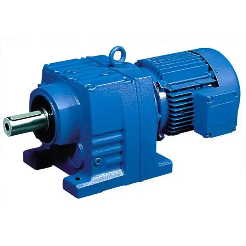
For conveyors, packaging equipment, mixers and other continuous-duty machinery, reliable selection starts with the complete torque-speed operating envelope.
How VFD Frequency Changes Inline Helical Gearbox Output Speed
A VFD changes the electrical frequency supplied to the motor. For an induction motor, synchronous speed is approximately:
Motor Speed = 120 × Frequency / Number of Poles
Actual motor speed is slightly lower because of slip.
The Inline Helical Gearbox then reduces motor speed according to its fixed mechanical ratio:
Output Speed = Motor Speed / Gear Ratio
For example, if a motor runs near 1,500 rpm and the Inline Helical Gearbox ratio is 30:1, nominal output speed is about 50 rpm. Reducing motor speed to 900 rpm gives approximately 30 rpm at the output.
The gearbox ratio remains 30:1. The VFD changes input speed; it does not create additional mechanical reduction.
Torque Should Be Checked Across the Complete Speed Range
Approximate gearbox output torque can be expressed as:
Output Torque ≈ Motor Torque × Gear Ratio × Gearbox Efficiency
This calculation is useful, but it is not sufficient for sizing an Inline Helical Gearbox.
Engineers should separate three load conditions:
• Continuous torque: torque required during normal steady operation.
• Starting torque: torque needed to accelerate the machine from standstill.
• Peak torque: short-duration torque caused by shock, jamming or process fluctuations.
A conveyor may require only 350 Nm during normal running but significantly more during a loaded start. In that case, motor rated torque alone does not define the drive requirement.
The allowable system torque is effectively limited by the lowest of:
Motor allowable torque → VFD-supported torque → Gearbox allowable torque
Short acceleration times also increase dynamic torque because the motor must accelerate both the driven load and rotating inertia.
Gear Ratio or VFD: Where Should Speed Reduction Come From?
This is one of the most important decisions when specifying an Inline Helical Gearbox with VFD.
| Drive Arrangement | Engineering Advantage | Main Concern |
| Higher gear ratio, motor near rated speed | Better motor cooling and motor utilization | Higher mechanical reduction required |
| Lower gear ratio, motor continuously at low frequency | Wide electronic adjustment | Low-speed thermal derating |
| Balanced ratio with moderate VFD range | Good speed flexibility and thermal margin | Requires accurate duty data |
The preferred approach is normally to use the Inline Helical Gearbox ratio to establish the basic speed and torque range, then use the VFD for process adjustment.
Running a motor continuously at very low frequency simply because the selected gearbox ratio is too low can create an unnecessary thermal problem.
Low-Speed Torque Is Often a Thermal Problem
Below base speed, a VFD-controlled induction motor can operate within a constant-torque region, but this does not mean full rated torque is automatically available at every low frequency.
Many industrial motors use a shaft-mounted cooling fan. As motor speed falls:
Motor Speed ↓ → Fan Airflow ↓ → Cooling Capacity ↓ → Winding Temperature ↑
For continuous low-speed, high-torque operation, consider:
• Motor manufacturer derating curves;
• Independent forced ventilation;
• Winding temperature sensors;
• Increased motor frame size;
• A higher Inline Helical Gearbox reduction ratio.
Above base frequency, the opposite problem occurs. The motor generally enters field weakening, where available torque decreases as speed rises. Increasing VFD frequency therefore cannot be assumed to provide both higher speed and full rated torque.
Match the VFD Control Mode to the Load
Different control modes produce different low-speed performance.
| VFD Control | Low-Speed Torque | Speed Regulation | Typical Use |
| V/f | Basic | Moderate | Simple constant-speed adjustment |
| Sensorless Vector | Stronger | Better | Conveyors, mixers, process machinery |
| Closed-Loop Vector | High | High | Very-low-speed or dynamic applications |
For many industrial Inline Helical Gearbox applications, sensorless vector control offers a practical balance between low-speed torque capability and system complexity.
Closed-loop control becomes more relevant when the machine needs very low stable speed, rapid torque response or tight speed accuracy.
Check Thermal Capacity, Not Just Mechanical Torque
A gearbox can be mechanically strong enough for a load and still operate above an acceptable temperature during long-duration service.
Thermal behavior depends on:
Transmitted power and internal losses;
• Operating speed;
• Lubricant viscosity;
• Ambient temperature;
• Mounting position;
• Duty cycle;
• Airflow around the housing;
• Starts and stops per hour.
Very low gearbox output speed also deserves attention because internal component speed affects lubricant distribution. There is no universal minimum safe RPM for every Inline Helical Gearbox. Lubrication method, mounting position and gearbox construction must be checked against manufacturer data.
VFD Commissioning Details That Protect the Gearbox
Mechanical reliability is also influenced by electrical setup.
Enter Correct Motor Data
Program the VFD with the actual:
• Rated voltage;
• Rated current;
• Frequency;
• Motor power;
• Rated RPM;
• Motor parameters required by the selected control mode.
Incorrect motor data can produce poor torque control or unnecessary current.
Avoid Excessively Short Acceleration Ramps
A very short acceleration time increases dynamic torque and may cause:
• VFD overcurrent;
• Coupling shock;
• Shaft loading;
• Gearbox peak torque overload.
Ramp time should therefore be selected from machine inertia and required process response, not simply set to the fastest possible value.
Monitor the Drive as a System
During commissioning and maintenance, record:
• Motor current;
• Motor temperature;
• Gearbox housing temperature;
• Abnormal noise;
• Vibration trend;
• Lubricant condition;
• Leakage and shaft alignment.
A hot Inline Helical Gearbox does not automatically mean an internal gearbox defect. Overloading, incorrect VFD parameters, poor ventilation or unsuitable lubrication can produce similar symptoms.

Standards Relevant to VFD-Controlled Gear Drives
For engineering verification, several IEC standards may apply:
• IEC 60034-1 — Motor ratings and duty classes;
• IEC TS 60034-25 —Motors used with converter-fed power drive systems;
• IEC 60034-18-41 — Motor insulation under PWM converter supply;
• IEC 61800-5-1 — Safety requirements for adjustable-speed power drive systems;
• IEC 61800-9-2 — Efficiency evaluation at power-drive-system level.
These standards help define the verification framework, but compliance should only be claimed when supported by the relevant product documentation or certification.
Data Required Before Selecting an Inline Helical Gearbox
Before choosing a gearbox, the supplier should receive more than motor power.
| Selection Data | Required Information |
| Machine | Conveyor, mixer, packaging line, etc. |
| Output speed | Minimum / normal / maximum RPM |
| Load | Continuous and peak torque |
| Motor | kW, rated RPM, current, voltage |
| VFD | Control mode and frequency range |
| Duty | Operating hours, starts/hour, load cycle |
| Environment | Ambient temperature, dust, moisture |
| Installation | Foot/flange mounting and orientation |
Mingye's R Series is the company's inline helical drive platform, alongside RF and RX configurations, with modular construction intended for different mounting and transmission requirements. Mingye also lists conveyors, packaging machinery and material-handling equipment among the applications for its helical gear motor range.
For a dependable Inline Helical Gearbox with VFD, start from the required machine speed and torque profile, then define the mechanical ratio, VFD operating range and thermal margin together.
For an application-specific configuration, review the Mingye R Series Helical Gear Motor range and provide your required power, output speed, ratio, torque, duty cycle and mounting conditions for a more accurate drive selection.
FAQs
Q1. Does Mingye offer an Inline Helical Gearbox for VFD-controlled applications?
Yes. Mingye's R Series helical gear motor platform can be considered for variable-speed industrial drive systems when the motor, VFD, gear ratio, torque demand and duty conditions are correctly matched.
Q2. Which Mingye series is suitable for an Inline Helical Gearbox application?
Mingye's R Series Helical Gear Motor is the primary inline helical configuration. RF and RX configurations are also available for different mounting and transmission requirements.
Q3. What information does Mingye need to select an Inline Helical Gearbox?
Customers should provide motor power, input speed, required output RPM, gear ratio, continuous torque, peak torque, duty cycle, mounting position and operating environment.
Q4. Can Mingye select an Inline Helical Gearbox for a conveyor system?
Yes. Conveyor applications should be evaluated using operating speed, loaded starting torque, continuous torque, acceleration time, operating hours and expected starts per hour.
Q5. Can a Mingye Inline Helical Gearbox operate continuously at low speed?
Continuous low-speed operation depends on the complete motor–VFD–gearbox system. Motor cooling, allowable torque, lubrication, ambient temperature and duty cycle should be checked before selection.
Share on Social:


Contact Us
In This Article
Right Angle Geared Motor: Matching Electrical Supply, Variable Speed and Braking
Oct 26, 2026
Planning a Bevel Reducer Installation: Turn Shaft Requirements Into a Practical Drive Layout
Oct 26, 2026
Choosing an Overhead Crane Gearbox by Its Hoisting or Travel Function
Oct 26, 2026
Replacing an Industrial Worm Gearbox: What to Keep and What to Reassess
Oct 25, 2026