


 Home /
Helical Bevel Gear Reducer Gear Accuracy and NVH Performance

Right Angle Geared Motor: Matching Electrical Supply, Variable Speed and Braking
Oct 26, 2026

Planning a Bevel Reducer Installation: Turn Shaft Requirements Into a Practical Drive Layout
Oct 26, 2026

Choosing an Overhead Crane Gearbox by Its Hoisting or Travel Function
Oct 26, 2026

Replacing an Industrial Worm Gearbox: What to Keep and What to Reassess
Oct 25, 2026
Noise and vibration in a Helical Bevel Gear Reducer are rarely caused by one component alone. In industrial applications, NVH performance is the result of gear geometry, tooth contact, shaft deflection, bearing support, housing stiffness, lubrication, operating speed, load and machine installation.
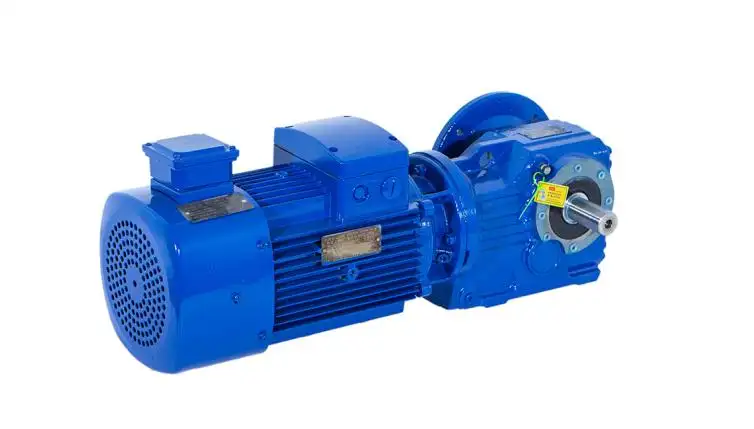
From Mingye's engineering perspective, a low-noise Helical Bevel Gear Reducer should therefore be evaluated as a complete drivetrain component rather than judged only by a catalog statement such as "low noise."
Why a Helical Bevel Gear Reducer Becomes Noisy at Certain Speeds
One common field condition is a reducer that runs normally at low speed but develops a noticeable whine within a narrow RPM range.
A key reason is gear mesh excitation.
Gear Mesh Frequency can be expressed as:
GMF = Number of Gear Teeth × Shaft Rotational Frequency
As input speed changes, the excitation frequency generated by gear engagement also changes. If this excitation approaches the natural frequency of the gearbox housing, mounting frame or driven machine, vibration can be amplified by resonance.
Typical symptoms include:
•Tonal whine at a specific RPM;
•Vibration that increases sharply after VFD speed changes;
•Low noise during no-load operation but higher vibration under torque;
•Sideband frequencies appearing around Gear Mesh Frequency;
•Noise that changes with temperature or operating time.
This is why a Helical Bevel Gear Reducer should be evaluated under realistic speed and load conditions.
Gear Accuracy Controls the Main NVH Excitation Source
The link between gear manufacturing quality and NVH is transmission error.
Transmission error is the discrepancy between ideal gear motion and actual motion during the meshing process. Depending on the way teeth have been designed, load can be moved from one tooth pair to the next. This creates dynamic mesh force.
The mechanical chain can be summarized as:
Gear Geometry Error → Transmission Error → Dynamic Mesh Force → Shaft/Bearing Vibration → Housing Response → Airborne Noise
The most relevant gear parameters are:
| Gear Parameter | Mechanical Effect | NVH Consequence |
| Pitch deviation | Unequal tooth spacing | Periodic mesh excitation |
| Profile deviation | Irregular load transfer | Gear whine and harmonics |
| Lead/helix deviation | Uneven load across tooth width | Localized vibration and contact stress |
| Runout | Periodic eccentric loading | Shaft-speed modulation |
| Backlash | Tooth-side clearance | Excessive clearance may cause impact or rattle |
For a Helical Bevel Gear Reducer, these errors should be considered together. A single accuracy number does not fully describe gearbox noise performance.
Why Gear Grinding Matters for Helical Bevel Gear Reducer NVH
Gear grinding is particularly important when operating speed, load stability and acoustic performance matter.
Compared with less precise finishing methods, grinding provides better potential control over:
•Tooth profile;
•Lead accuracy;
•Pitch consistency;
•Surface finish;
•Contact pattern stability.
Mingye applies carburizing and quenching to gears and gear shafts, followed by gear grinding. The K Series product information specifies HRC 58–62 gear hardness and states that tooth profile, lead and pitch are inspected to Grade 6 accuracy.
These processes do not create a fixed noise value, but they help control the geometric variables that influence transmission error and long-term gear contact.
Gear Hardness Does Not Equal Low Noise
HRC 58–62 should mainly be understood as a durability parameter.
Higher surface hardness helps improve:
•Resistance to pitting;
•Tooth surface wear resistance;
•Contact fatigue performance;
•Retention of gear geometry over service life.
It should not be interpreted as "higher hardness means lower dB."
Helical Bevel Gear Reducer vs. Worm Reducer for Right-Angle Drives
Both systems can provide 90° power transmission, but their mechanical behavior differs.
| Selection Factor | Helical Bevel Gear Reducer | Worm Reducer |
| Tooth contact | Rolling/sliding combination | Higher sliding component |
| Efficiency | Generally higher | Can decrease at high ratios |
| Heat generation | Typically lower | Sliding losses may increase heat |
| Continuous-duty behavior | Well suited when correctly sized | Thermal capacity requires attention |
| NVH source | Gear mesh frequency and structural response | Sliding/contact and mesh effects |
| Typical use | Efficient industrial right-angle drives | Compact or high-ratio applications |
It is inaccurate to state that every Helical Bevel Gear Reducer is always quieter than a worm gearbox. Noise depends on accuracy, ratio, speed, loading, lubrication and installation.
System Matching Is as Important as Gear Accuracy
A precision reducer installed in a poorly designed drivetrain can still generate unacceptable vibration.
When Mingye engineers evaluate a Helical Bevel Gear Reducer application, the following operating data should be considered together:
•Motor power and input RPM;
•Required output speed;
•Reduction ratio;
•Continuous and peak torque;
•Duty cycle;
•Radial and axial output loads;
•Motor and coupling arrangement;
•Mounting position;
•Ambient and operating temperature;
•Machine-frame stiffness.
VFD Operation Requires Special Attention
Variable-frequency drives continuously shift the operating speed of the reducer. As speed changes, Gear Mesh Frequency and shaft-order frequencies also move.
A machine may therefore pass through a resonance range even though the Helical Bevel Gear Reducer is mechanically healthy.
For VFD applications, engineers should identify:
•Normal operating speed range;
•Acceleration/deceleration profile;
•Continuous low-speed duty;
•Resonant RPM zones;
•Cooling requirements.
Installation Errors Can Override Precision Manufacturing
Field NVH problems often originate outside the gearbox.
Important installation checks include:
•Verify motor and reducer alignment;
•Prevent housing distortion from uneven mounting surfaces;
•Confirm coupling concentricity;
•Avoid excessive overhung radial load;
•Tighten mounting bolts uniformly;
•Use the correct lubricant for temperature and duty;
•Monitor bearing and seal condition.
A low-noise Helical Bevel Gear Reducer cannot compensate for a flexible foundation, misaligned shaft or damaged coupling.
Using Vibration Data to Separate Gear and Bearing Problems
Not every vibration peak indicates gear damage.
Gear-related problems often appear around:
•Gear Mesh Frequency;
•GMF harmonics;
•GMF sidebands;
•Shaft rotational orders.
Bearing defects may appear at characteristic bearing frequencies, while unbalance is often dominated by 1× shaft speed.
For maintenance teams, trending is usually more useful than one isolated reading. Rising vibration combined with temperature increase, lubricant contamination or changing sidebands may indicate progressive deterioration.
How Buyers Should Verify Helical Bevel Gear Reducer NVH
A supplier's noise value is meaningful only when test conditions are defined.
Buyers should request:
•Input RPM;
•Operating ratio;
•Applied torque;
•Mounting arrangement;
•Lubricant and temperature;
•Microphone distance;
•Sound-pressure or sound-power method;
•Vibration measurement location;
•Test standard.
For gearbox sound testing, ISO 8579-1 provides a framework for airborne sound measurement. Gear unit vibration can also be evaluated using applicable guidance from ISO 20816-9.
Gear accuracy standards should not be confused with complete gearbox NVH performance. Gear grade describes geometry; it does not directly specify a fixed sound level.
Mingye K Series for Noise-Sensitive Right-Angle Transmission
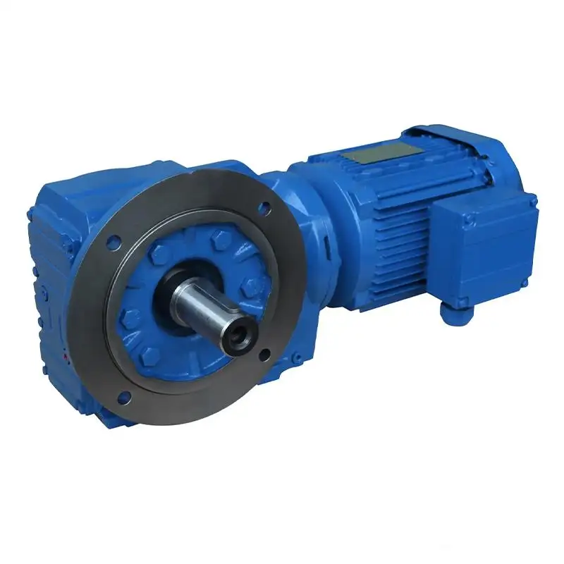
Mingye's K/KA/KAF37–187 Helical Bevel Gear Reducer combines helical and bevel gearing for compact 90° power transmission. Its manufacturing process includes carburizing and quenching, HRC 58–62 tooth hardness, gear grinding and inspection of tooth profile, lead and pitch.
For engineers selecting a Helical Bevel Gear Reducer, Mingye recommends evaluating the reducer together with the actual motor, speed, ratio, torque, mounting and duty cycle rather than selecting from rated power alone.
For right-angle drives where efficiency, durability and NVH stability must be balanced, the Mingye K Series Helical Bevel Gear Motor provides a practical basis for further application-specific selection.
FAQs
Q1. What Helical Bevel Gear Reducer series does Mingye offer?
Mingye offers the K/KA/KAF37–187 Series Helical Bevel Gear Reducer, combining helical and bevel gearing for compact 90-degree industrial transmission.
Q2. How does Mingye control gear accuracy in its Helical Bevel Gear Reducer?
Mingye uses gear grinding and inspects critical gear geometry such as tooth profile, lead and pitch. Its K Series product information states Grade 6 gear accuracy.
Q3. What is the gear hardness of Mingye's Helical Bevel Gear Reducer?
Mingye's gears and gear shafts are carburized and quenched to approximately HRC 58–62, supporting wear resistance and contact durability.
Q4. Does Mingye's Grade 6 gear accuracy guarantee a specific noise level?
No. Gear accuracy can help reduce transmission error, but actual NVH also depends on speed, torque, bearings, lubrication, housing stiffness, mounting and the driven machine.
Q5. Why does Mingye use gear grinding for the K Series?
Gear grinding helps improve tooth profile, lead, pitch consistency and surface finish, all of which are relevant to stable gear engagement and vibration control.
Share on Social:


Contact Us
In This Article
Right Angle Geared Motor: Matching Electrical Supply, Variable Speed and Braking
Oct 26, 2026
Planning a Bevel Reducer Installation: Turn Shaft Requirements Into a Practical Drive Layout
Oct 26, 2026
Choosing an Overhead Crane Gearbox by Its Hoisting or Travel Function
Oct 26, 2026
Replacing an Industrial Worm Gearbox: What to Keep and What to Reassess
Oct 25, 2026