


 Home /
Bevel Speed Reducer Ratio Selection: How to Choose Between 1:1, 2:1, 3:1 and 5:1

Right Angle Geared Motor: Matching Electrical Supply, Variable Speed and Braking
Oct 26, 2026

Planning a Bevel Reducer Installation: Turn Shaft Requirements Into a Practical Drive Layout
Oct 26, 2026

Choosing an Overhead Crane Gearbox by Its Hoisting or Travel Function
Oct 26, 2026

Replacing an Industrial Worm Gearbox: What to Keep and What to Reassess
Oct 25, 2026
Selecting a Bevel Speed Reducer ratio is not simply a choice between "more speed" and "more torque." In an industrial drive, the ratio determines output rpm and theoretical torque multiplication, but the final gearbox must also withstand continuous torque, startup peaks, shock loading, bearing forces and thermal conditions.
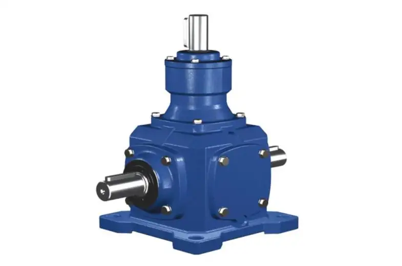
For Mingye, correct Bevel Speed Reducer selection therefore starts with the machine duty—not with the gearbox catalog.
Calculate the Required Ratio From Machine Speed
The first engineering question is straightforward:
Ratio = Input Speed ÷ Required Output Speed
For a 1,500 rpm motor:
| Ratio | Theoretical Output Speed | Main Design Purpose |
| 1:1 | 1,500 rpm | Change shaft direction without nominal reduction |
| 2:1 | 750 rpm | Moderate speed reduction |
| 3:1 | 500 rpm | Balanced speed reduction and torque multiplication |
| 5:1 | 300 rpm | Lower output speed and greater mechanical reduction |
This calculation gives a preliminary Bevel Speed Reducer ratio, not the final gearbox selection.
A common engineering mistake is to calculate 1,500 ÷ 300 = 5 and immediately specify a 5:1 unit. The ratio may be correct, but the selected reducer can still be undersized if the load has high starting torque or frequent shock loads.
What a Higher Bevel Speed Reducer Ratio Changes
For an ideal reduction stage:
Output Torque ≈ Input Torque × Ratio × Efficiency
Motor torque can be estimated from:
T = 9550 × P ÷ n
where:
•T = torque in Nm
•P = motor power in kW
•n = rotational speed in rpm
Increasing the Bevel Speed Reducer ratio reduces output speed and increases theoretical output torque. However, usable torque is limited by the reducer itself.
The final capacity depends on factors such as:
•Spiral bevel tooth contact stress
•Tooth-root bending strength
•Shaft torsional capacity
•Bearing radial and axial loads
•Lubrication condition
•Housing rigidity
•Operating temperature
•Duty cycle and service factor
Therefore, a 5:1 ratio does not mean that any input torque can simply be multiplied by five safely.
1:1, 2:1, 3:1 and 5:1 Are Different Engineering Choices
1:1: Direction Change Without Reduction
A 1:1 Bevel Speed Reducer is primarily a right-angle transmission device.
It is suitable when the design needs:
•Intersecting or 90° shaft arrangement
•Nearly unchanged output speed
•Compact change of power direction
•Mechanical synchronization between shafts
In a 1:1 bevel pair, the gear geometry is also more symmetrical than in higher-ratio combinations.
2:1 vs. 3:1: Speed or Torque Priority
A 2:1 ratio retains more output speed, while 3:1 provides greater reduction.
The selection should be based on the driven machine:
2:1 may be preferred when:
•Cycle speed is important
•Required output rpm remains relatively high
•Load torque is moderate
3:1 may be preferred when:
•Lower machine speed is required
•More mechanical torque multiplication is useful
•The driven load has higher resistance
Neither ratio is inherently "better."
3:1 vs. 5:1: Avoid Oversizing the Ratio
Moving from 3:1 to 5:1 lowers output speed from approximately 33% to 20% of input speed.
That can benefit slower conveyors, mixers or processing mechanisms, but higher ratio alone should not be used as a substitute for proper gearbox sizing.
Engineers should check:
•Continuous output torque
•Starting torque
•Maximum transient torque
•Starts per hour
•Reversing frequency
• Operating hours per day
Ratio Selection Must Include Load Behavior
At Mingye, a Bevel Speed Reducer application should be evaluated using more than nominal motor power.
Continuous Torque
This is the steady torque required once the equipment reaches normal operating speed.
Starting Torque
Conveyors carrying material, mixers starting under product load and indexing mechanisms may require significantly higher startup torque.
Shock and Peak Torque
Severe conditions may be found in non-normal operating conditions:
•Conveyor jams
•Abrupt material build-up
•Emergency stops
•Reverse motion
•Intermittent indexing
•Rapid acceleration
The Bevel Speed Reducer must be designed for these transient loads to avoid excess tooth stress and bearing overload.
Mechanical Ratio vs. VFD Speed Control
Modern machines often combine a gearbox with variable-frequency motor control.
| Drive Strategy | Advantage | Engineering Consideration |
| 5:1 Bevel Speed Reducer | Strong fixed mechanical reduction | Limited speed flexibility |
| 3:1 + VFD | Wider operating speed range | Motor performance at low frequency must be checked |
| 2:1 + VFD | Higher mechanical output speed | Less torque multiplication from gearing |
A higher mechanical ratio is often practical for fixed-speed equipment. A lower ratio with VFD control may be preferable when operating speed must change during production.
The gearbox and motor should therefore be treated as one drive system.
Installation Conditions Can Override a Correct Ratio
Even a correctly selected Bevel Speed Reducer can develop noise, temperature rise or premature wear if the installation is poor.
Spiral bevel gears generate complex tooth forces. These forces are transferred through shafts and bearings, so installation should control:
•Shaft alignment
•Coupling alignment
•Mounting surface rigidity
•Radial and axial shaft loads
•Lubricant quantity and viscosity
•Operating temperature
•Input speed
Incorrect alignment can shift the tooth contact pattern toward an edge of the gear face, increasing localized stress and accelerating pitting or wear.
Lubrication is equally important. Insufficient oil film can increase friction, tooth temperature and scuffing risk, particularly under high load.
Match the Ratio to the T Series Size
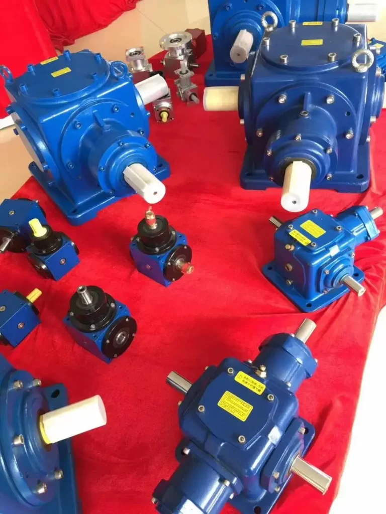
Mingye's T Series Spiral Bevel Gear Reducer is designed for intersecting-shaft power transmission and is available in:
T2, T4, T6, T7, T8, T10, T12, T16, T20 and T25
Standard transmission ratios include:
1:1, 1.5:1, 2:1, 2.5:1, 3:1, 4:1 and 5:1
Mingye publishes average transmission efficiency reaching approximately 98%, while the spiral bevel tooth form provides progressive engagement for smoother torque transfer.
However, ratio and frame size should be selected separately.
Before confirming a T Series Bevel Speed Reducer, Mingye recommends defining:
•Motor power and input rpm
•Required output rpm
•Continuous load torque
•Startup and peak torque
•Operating hours per day
•Starts and reversals per hour
•Shaft arrangement
•Mounting orientation
•Ambient conditions
The selected unit should then be checked against the applicable rated torque, permissible speed and installation conditions.
The Gearbox Needs More Than a Ratio
When designing solutions for demanding situations I prefer to use a combination of ratio calculations and recognized engineering methods.
Bevel gear design commonly considers:
•ISO 23509 — bevel and hypoid gear geometry
•ISO 10300 — bevel gear load capacity
•Surface durability and pitting resistance
•Tooth-root bending strength
•Gear accuracy and contact quality
These checks explain why Bevel Speed Reducer selection cannot end with rpm calculation alone.
Choose the Bevel Speed Reducer as a Complete Drive
A reliable Bevel Speed Reducer selection follows a clear sequence:
Required Output Speed → Ratio → Torque → Peak Load → Duty Cycle → Gearbox Size → Installation → Lubrication → Verification
A 1:1 ratio suits directional transmission, 2:1 favors higher machine speed, 3:1 provides a balanced reduction, and 5:1 offers greater mechanical reduction. The correct choice is the ratio that fits the complete operating condition.
For OEMs and industrial equipment builders, Mingye's T Series provides multiple standard ratios and frame sizes for compact spiral bevel transmission. Review the available configurations and discuss your motor, speed, torque and duty requirements with Mingye before finalizing the Bevel Speed Reducer selection.
FAQs
Q1: What Bevel Speed Reducer ratios does Mingye offer?
Mingye's T Series Spiral Bevel Gear Reducer is available with standard ratios including 1:1, 1.5:1, 2:1, 2.5:1, 3:1, 4:1 and 5:1.
Q2: Which Mingye Bevel Speed Reducer ratio should I choose?
The ratio should be selected from motor input speed, required output speed, load torque, startup conditions and duty cycle rather than ratio alone.
Q3: Does Mingye offer a 1:1 Bevel Speed Reducer?
Yes. A 1:1 configuration is useful when the main requirement is changing power-transmission direction while maintaining approximately the same rotational speed.
Q4: What Mingye T Series sizes are available?
The T Series includes T2, T4, T6, T7, T8, T10, T12, T16, T20 and T25 frame sizes.
Q5: Can Mingye help select a Bevel Speed Reducer for a specific machine?
Buyers can provide motor power, input rpm, required output rpm, torque, duty cycle, mounting arrangement and load conditions for more accurate selection.
Share on Social:


Contact Us
In This Article
Right Angle Geared Motor: Matching Electrical Supply, Variable Speed and Braking
Oct 26, 2026
Planning a Bevel Reducer Installation: Turn Shaft Requirements Into a Practical Drive Layout
Oct 26, 2026
Choosing an Overhead Crane Gearbox by Its Hoisting or Travel Function
Oct 26, 2026
Replacing an Industrial Worm Gearbox: What to Keep and What to Reassess
Oct 25, 2026