


 Home /
Service Factor for Gear Reduction Motors: Why Motor Power Alone Is Not Enough
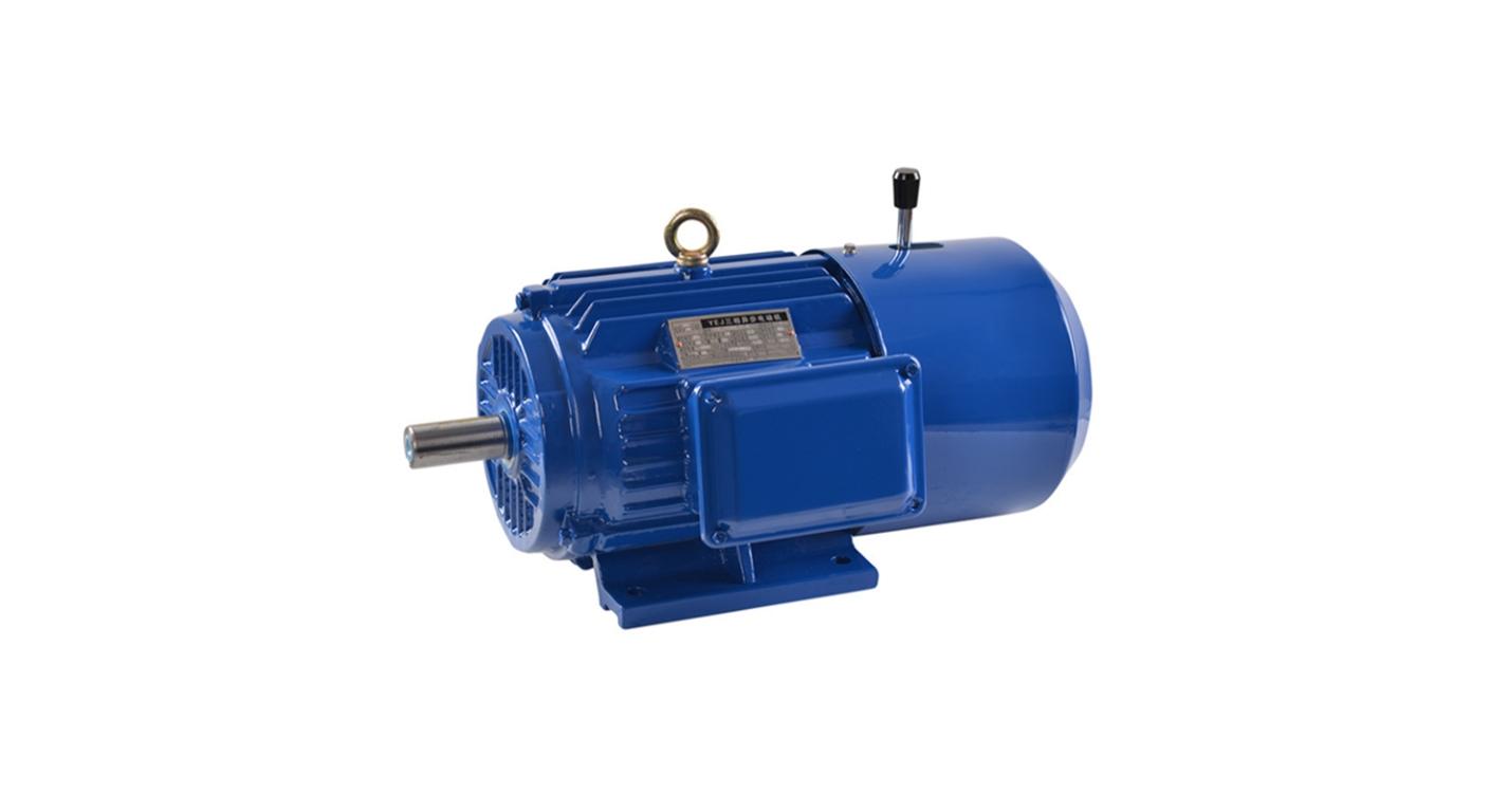
Right Angle Geared Motor: Matching Electrical Supply, Variable Speed and Braking
Oct 26, 2026
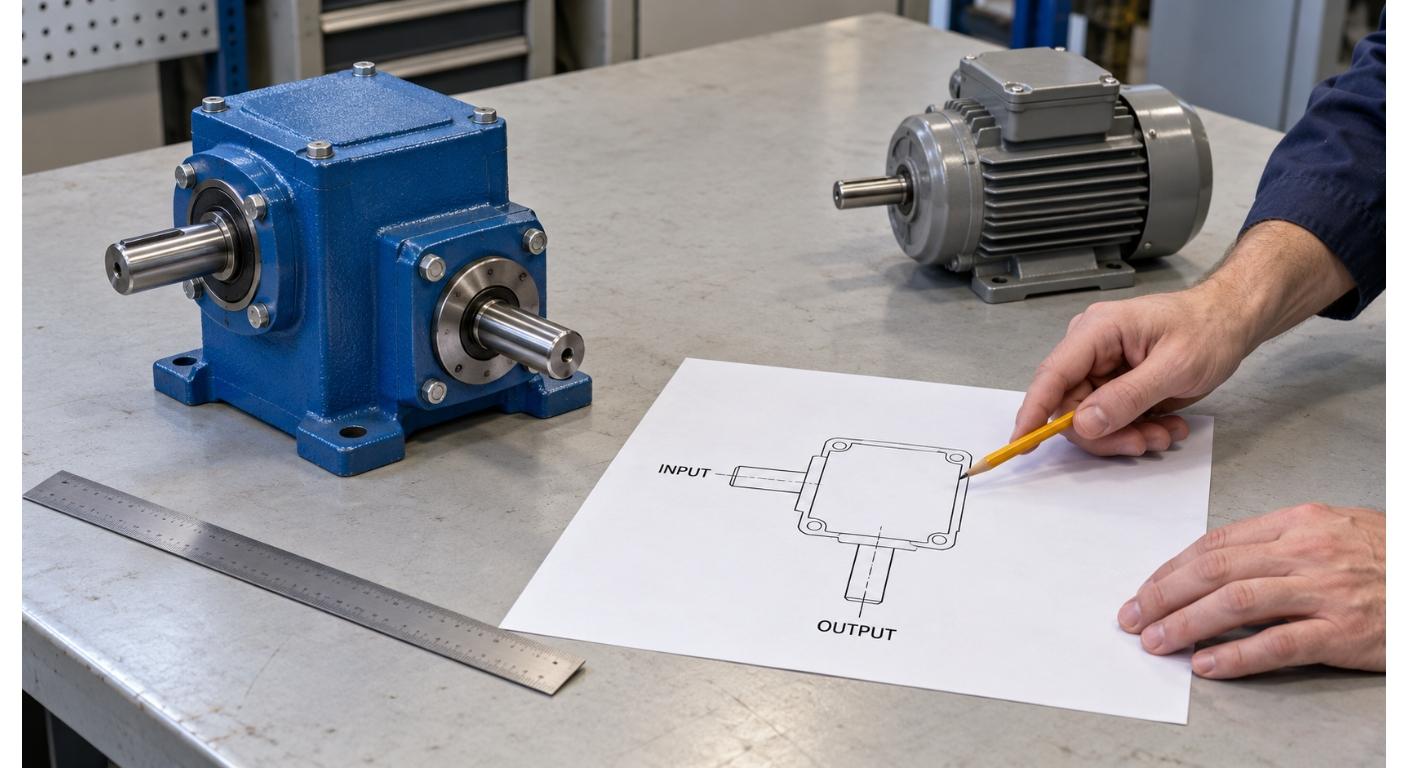
Planning a Bevel Reducer Installation: Turn Shaft Requirements Into a Practical Drive Layout
Oct 26, 2026
Choosing an Overhead Crane Gearbox by Its Hoisting or Travel Function
Oct 26, 2026
Replacing an Industrial Worm Gearbox: What to Keep and What to Reassess
Oct 25, 2026
Two conveyor drives in the same plant use 2.2 kW motors. One runs a packaging belt — uniform load, 8 hours a day, occasional starts. The other drives a bucket elevator — shock loads from material loading, 16 hours a day, frequent starts under full load. Both have the same motor power. But the second application needs a larger gearbox — not because the torque is higher, but because the operating conditions are more severe.
This is the role of the service factor — a multiplier that accounts for the severity of the application and ensures the gearbox has adequate mechanical capacity for the actual operating conditions, not just the nominal load. This article explains what service factor is, why the same motor power can require different gearbox sizes, how different standards and manufacturers define it, and how to use it correctly in the selection process.
What Service Factor Is — and What It Is Not
The Definition
The service factor (SF), also called application factor or overload factor, is a multiplier applied to the nominal load torque to determine the required gearbox capacity. In simplified terms:
Required Gearbox Torque = Nominal Load Torque × Service Factor
If the application has a nominal load torque of 200 N·m and the service factor is 1.5, the gearbox must be rated for at least 300 N·m of output torque.

What It Is Not
Service factor is not a single “safety margin” that can be applied uniformly. It is a composite factor that accounts for multiple aspects of the application:
- The severity of the load (uniform, moderate shock, heavy shock)
- The duration of operation (hours per day)
- The frequency of starts and stops
- Whether starts are under full load
- Whether the application involves reversing
- The inertia ratio between the load and the motor
Service factor is not the same as thermal capacity. The service factor addresses the mechanical strength of the gearbox — the gear tooth bending strength and surface durability (pitting resistance). Thermal capacity addresses the heat balance — whether the gearbox and motor can dissipate the heat generated during operation. Both must be satisfied: a gearbox that is mechanically adequate but thermally overloaded will fail from overheating; a gearbox that is thermally adequate but mechanically overloaded will fail from gear tooth fatigue.
Service factor values are not interchangeable across sources. The term “service factor” is not implemented identically across every manufacturer, catalog or standard. Use the definitions and tables applicable to the specific gearbox series rather than transferring a factor from another source.
Not sure which service factor applies to your application? Send your hours per day, starts per hour, load type (uniform / moderate shock / heavy shock), and whether starts are under full load. We can check the appropriate service factor from the selection table and confirm whether the proposed gearbox size is adequate for your actual operating conditions.
Factors That Determine the Service Factor
Load Class
The most fundamental factor is the nature of the driven load:
| Load Class | Description | Examples |
| Class I (Uniform) | Steady load, smooth starts, no shock | Conveyors with uniform material flow, fans, blowers, centrifugal pumps |
| Class II (Moderate shock) | Moderate load variations, occasional shock | Mixers with varying viscosity, bucket elevators, reciprocating pumps |
| Class III (Heavy shock) | Severe load variations, frequent shock, high inertia | Crushers, mills, hammer mills, heavy-duty reciprocating equipment |
The load class is often characterized by the inertia acceleration coefficient — the ratio of the load’s moment of inertia to the motor’s moment of inertia. A higher inertia ratio means the motor must deliver more torque during acceleration to bring the load up to speed, which increases the mechanical stress on the gearbox. High load inertia can increase acceleration torque and may affect drive selection; provide the inertia information when available and use the manufacturer’s selection method.
Operating Hours per Day
More operating hours mean more cumulative stress on the gear teeth and bearings. A gearbox running 24 hours a day accumulates three times as many load cycles as one running 8 hours a day, which accelerates fatigue. The relationship between cycle count and fatigue life is not linear — but more cycles always mean faster accumulation of fatigue damage.

Start Frequency
Every start introduces a torque transient — the motor must accelerate the load from rest, which requires torque above the continuous rating. Frequent starts mean frequent torque transients, which fatigue the gear teeth and bearings.
The distinction between S3 and S4 duty is relevant here: In S3 (intermittent periodic duty), the starting current has negligible effect on temperature rise. In S4 (intermittent periodic duty with starting), the starting current significantly affects temperature rise. An application with frequent starts may need to be classified as S4 rather than S3 — which changes both the service factor and the thermal selection.
Full-Load vs. Partial-Load Start
Starting under full load is more demanding than starting under partial load. A conveyor that starts empty and gradually fills is less demanding than one that must start with a full belt of material resting on it.
Reversing
Applications that require frequent direction changes (reversing) impose additional stress on the gear teeth — the load transitions from one face of the tooth to the other, and the backlash in the system creates impact loads during each reversal.
Ambient Temperature
Some service factor systems include a separate environmental multiplier. For example, SEW’s system uses fb = fb1 (operating condition factor) × fb2 (ambient temperature factor). Other manufacturers may use different factor structures — the specific method depends on the manufacturer’s gear design and testing data. Higher ambient temperatures require a higher overall factor because the gearbox’s thermal margin is reduced.
Why the Same kW Can Require Different Gearbox Sizes
Consider two applications, both with 2.2 kW motors:
| Parameter | Application A (Packaging Conveyor) | Application B (Bucket Elevator) |
| Motor power | 2.2 kW | 2.2 kW |
| Load class | Uniform (Class I) | Moderate shock (Class II) |
| Hours/day | 8 | 16 |
| Starts/hour | 2 | 20 |
| Full-load start? | No | Yes |
| Reversing? | No | No |
| Ambient temperature | 25°C | 35°C |
Application A’s operating conditions are mild — uniform load, short hours, infrequent starts, partial-load start. A lower service factor may be applicable.
Application B’s conditions are more severe — shock loads, long hours, frequent starts under full load. A higher service factor is likely required.
If Application A needs 200 N·m of nominal output torque, the gearbox must be rated for at least 200 × SF_A N·m. If Application B needs the same 200 N·m, the gearbox must be rated for at least 200 × SF_B N·m — where SF_B is significantly higher than SF_A due to the more severe operating conditions. The result is a larger gearbox, even though the motor power and nominal torque are the same.
This is why motor power alone is not a sufficient specification. Two applications with identical motor power and identical nominal torque can require different gearbox sizes because the service factor — driven by the operating conditions — is different.
How to Use Service Factor Correctly in Selection
Step 1: Determine the Load Class
Classify the driven load as uniform (I), moderate shock (II), or heavy shock (III). If the load has high inertia (the driven equipment has a large rotating mass that must be accelerated), calculate the inertia acceleration coefficient.
Step 2: Determine the Operating Pattern
Record the operating hours per day, the number of starts per hour, whether starts are under full load, and whether the application involves reversing.
Step 3: Look Up the Service Factor in the Manufacturer’s Table
Use the specific manufacturer’s selection table — not a generic table from a textbook or a different brand. The table will cross-reference the load class, operating hours, and start frequency to produce the required service factor.
Do not assume values across manufacturers. A service factor of 1.5 in one manufacturer’s table may correspond to a different set of operating conditions than 1.5 in another’s. The tables are calibrated to the specific gear designs, materials, and manufacturing tolerances of each manufacturer.
Step 4: Calculate the Required Gearbox Torque
Multiply the nominal load torque by the service factor to get the required gearbox rated torque.
Step 5: Verify Against the Selection Table
Check the manufacturer’s selection table to find a gearbox model and ratio whose rated output torque meets or exceeds the required torque. This is the mechanical check.
Step 6: Verify Thermal Capacity
Separately from the mechanical check, verify that the gearbox and motor can dissipate the heat generated under the actual operating conditions. Mechanical capacity and thermal suitability are separate checks; verify both using the data and method provided for the selected gearbox and motor.
Both checks must pass. A gearbox that passes the mechanical check but fails the thermal check will overheat. A gearbox that passes the thermal check but fails the mechanical check will fail from gear or bearing fatigue.
Comparing suppliers and getting different recommendations? Send us two data sheets from different manufacturers with the same application requirements. We can review the rated torque, service factor, and thermal capacity from each — and help you understand why the recommendations may differ.
Common Mistakes — Quick Checklist
- Using a generic value (e.g., “always 1.5”) without consulting the manufacturer’s table → may under- or over-specify
- Copying from a different manufacturer → service factor definitions are not interchangeable across brands
- Ignoring thermal capacity → service factor covers mechanical strength only; thermal check is separate (Step 6)
- Not communicating operating conditions → supplier defaults to uniform load assumption, which may be inadequate
For a detailed framework on distinguishing application mismatch from manufacturing defect, see our failure analysis guide.
What to Send a Supplier for Correct Service Factor Selection
| Parameter | Why It Matters |
| Load type (uniform / moderate shock / heavy shock) | Determines the base service factor |
| Operating hours per day | Affects cumulative stress |
| Starts per hour | Affects mechanical and thermal cycling |
| Full-load start? (yes/no) | Determines starting torque demand |
| Reversing? (yes/no) | Affects gear tooth fatigue |
| Inertia ratio (if known) | Determines acceleration torque demand |
| Ambient temperature | Affects thermal margin and environmental factor |
| Nominal load torque or load description | Base for service factor multiplication |
Not sure which service factor applies to your application? Send your hours per day, starts per hour, load type (uniform / moderate shock / heavy shock), and whether starts are under full load. We can check the appropriate service factor from the selection table and confirm whether the proposed gearbox size is adequate — or whether a larger size is needed for your actual operating conditions.
Share on Social:


Contact Us
In This Article
Right Angle Geared Motor: Matching Electrical Supply, Variable Speed and Braking
Oct 26, 2026
Planning a Bevel Reducer Installation: Turn Shaft Requirements Into a Practical Drive Layout
Oct 26, 2026
Choosing an Overhead Crane Gearbox by Its Hoisting or Travel Function
Oct 26, 2026
Replacing an Industrial Worm Gearbox: What to Keep and What to Reassess
Oct 25, 2026