


 Home /
When a Right Angle Gear Motor Solves a Machine Layout Problem — and When It Does Not
Vertical-Axis Drives After Power Loss: Which Holding and Brake Data Must OEMs Verify?
Oct 14, 2026
Indexing Packaging Machines: Calculating Acceleration Torque From a Motion Profile
Oct 14, 2026

Changing an NMRV Worm Gearbox Ratio: Can You Keep the Existing Motor?
Oct 14, 2026
How to Check Overhung Load When a Chain Sprocket Is Moved Along a Gearbox Output Shaft
Oct 14, 2026
For example, consider a design engineer laying out a new packaging machine. The conveyor drive needs to sit at the end of a 600 mm wide frame, but an inline motor and gearbox assembly would extend 350 mm beyond the frame edge — into the operator walkway. The obvious solution is a right-angle gear motor, which turns the motor 90 degrees and tucks it alongside the conveyor instead of sticking out past it. Problem solved, right?
Maybe. The right-angle gear motor does solve the footprint problem, but it introduces its own set of trade-offs: efficiency loss (especially with worm gearing), additional heat, reaction torque management, and potentially higher cost. In some cases, these trade-offs are worth it. In others, a closer look at the layout reveals that an inline or parallel-shaft drive could work with a minor frame redesign — avoiding the right-angle complications entirely.
This article is not a sales pitch for right-angle gear motors. It is a framework for deciding whether a 90-degree drive genuinely solves your layout problem — or whether it creates new ones while solving the original.
Layout Constraints That Make 90-Degree Drives Valuable
Before examining the trade-offs, let us be clear about when a right-angle gear motor is the right answer. There are genuine layout constraints that make 90-degree transmission necessary, not merely convenient.

Equipment Width Restrictions
The most common driver for right-angle drives is width. An inline motor-and-gearbox assembly extends along the output shaft axis. If the machine frame is narrow, or if the space beside the machine is an operator walkway, a maintenance access area, or adjacent equipment, the inline drive’s length becomes a problem. A right-angle gear motor redirects the motor perpendicular to the output shaft, so the motor body sits alongside the drive rather than behind it.
This is particularly relevant for:
- Conveyor systems with limited frame width
- Crane and trolley travel drives with narrow track gauge (the drive package must fit within the rail envelope)
- Packaging and processing lines where operators need access along the full length of the machine
Vertical Output Requirements
Some applications require the output shaft to point vertically — up or down — while the motor sits horizontally. Lifts, agitators, screw conveyors, and vertical mixers all fall into this category. A right-angle gear motor (specifically a helical-bevel or worm design) provides the 90-degree turn without requiring a separate miter box or bevel gearbox in the drive train.
Corner-Mounted and U-Shaped Layouts
In modular machine designs, the drive may need to sit in a corner to free up the front face for operator access, material flow, or sensor mounting. A right-angle gear motor allows the motor to be positioned perpendicular to the output, tucking it into a corner or along a side panel.
Height Reduction
In some cases, the right-angle configuration reduces the overall height of the drive package. If an inline motor sits on top of the gearbox and the total height exceeds the available vertical space, a right-angle configuration can position the motor beside the gearbox, reducing the stack height.
What Right-Angle Costs You
The 90-degree turn is not free. Every advantage listed above comes with trade-offs that need to be weighed against the layout benefit.
Efficiency
Right-angle geometry does not automatically mean poor efficiency. The real trade-off depends mainly on gear architecture, ratio, number of stages and operating point.
- Helical-bevel right-angle: Generally offers higher efficiency than worm gear designs. Actual values depend on ratio, stages, and load.
- Worm gear right-angle: Efficiency is lower and varies significantly with ratio, load, and lubrication. At high ratios, worm gear efficiency can drop substantially.
- Inline or parallel-shaft: Typically the most efficient option, as the gear mesh is simpler and the friction losses are lower.
When this matters: For continuous-duty applications, even a modest efficiency difference can add up to thousands of kWh per year for a continuously running motor. For intermittent-duty applications, the efficiency loss may be negligible.
Heat
Lower efficiency means more input power is converted to heat rather than useful output. Worm gear drives, with their sliding contact mechanism, generate more heat than rolling-contact helical-bevel drives, which in turn generate more heat than inline drives. The gearbox must dissipate this heat through its housing surface to the surrounding air. If the installation is in a hot environment or an enclosed space, the right-angle drive’s additional heat can push the operating temperature into a range that degrades the lubricant and shortens bearing life.
Reaction Torque Management
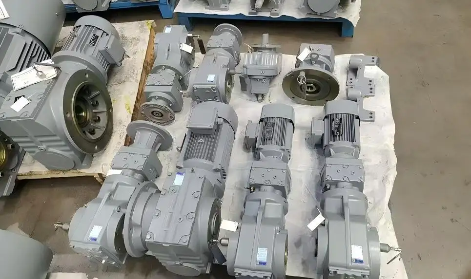
A foot-mounted or flange-mounted gearbox transmits its reaction torque through the mounting bolts to the machine frame. This is straightforward and does not require additional hardware.
A shaft-mounted gearbox (hollow shaft, mounted directly on the driven shaft) requires a separate torque arm or reaction bracket to absorb the reaction torque. This adds a mechanical component that must be designed, installed, and maintained. If the torque arm is undersized, improperly installed, or fatigues over time, the gearbox can rotate under load and cause damage.
Cost
Right-angle gear motors are generally more expensive than inline or parallel-shaft units of equivalent power and ratio. The bevel or worm gearing is more complex to manufacture, and the housing design is more complicated. For high-ratio applications, worm gear motors can be cost-competitive (single-stage worm vs. multi-stage inline), but for moderate ratios, the inline option is typically cheaper.
Maintenance Complexity
Right-angle gear motors may require more maintenance attention than inline drives:
- Worm gear units may need more frequent oil changes due to thermal stress on the lubricant
- Hollow shaft installations require torque arm inspection
- Mounting position changes require oil level adjustment
- The 90-degree configuration may make some maintenance points (drain plugs, breathers) harder to access depending on the installation orientation
Space Savings: Look Beyond the Gearbox Length
One of the most common errors in layout planning is assuming that a right-angle gear motor will save a specific amount of space based on the gearbox length alone. The actual space savings — or lack thereof — depends on the complete drive package, not just the gearbox.
What to Measure for Total Space
| Dimension | What It Includes |
| Gearbox length (along output axis) | The gearbox housing dimension in the output direction |
| Motor extension (perpendicular to output) | The motor body extends sideways from the gearbox — does this fit within the available width? |
| Output shaft and coupling space | For solid shaft: coupling + driven shaft extension. For hollow shaft: the gearbox slides onto the driven shaft, but the motor still extends sideways |
| Maintenance clearance | Space for oil checks, drain access, breather inspection, bolt access for removal |
| Cooling clearance | Airflow space around the motor and gearbox housing for heat dissipation |
| Torque arm space (if hollow shaft) | The torque arm extends from the gearbox to the machine frame — this needs space |
Example: For illustration, a right-angle unit might save 200 mm in the output direction compared to an inline drive, but the motor body now extends 180 mm to the side. If the machine has 200 mm of side clearance, the right-angle drive fits. If the machine has only 100 mm of side clearance (because of an adjacent conveyor or a wall), the right-angle drive does not fit — and the “savings” are illusory.
The one-line test: If the motor’s sideways extension fits within your available side clearance, right-angle saves space. If it does not, the “savings” are illusory — you have moved the space problem, not solved it.
Five Questions to Ask Before Choosing a Right-Angle Drive
Use these questions as a decision filter. If you answer “yes” to the first question and the subsequent questions do not disqualify the right-angle option, proceed. If any question reveals a problem, reconsider the layout.

Question 1: Does the Machine Layout Genuinely Require 90-Degree Transmission?
This is the gating question. If the output shaft and motor shaft can be on the same axis (or parallel axes), an inline or parallel-shaft gearbox is simpler, more efficient, and typically cheaper. The right-angle option should be selected because the layout demands it — not because it is the default choice.
Test: Sketch the machine layout showing the motor position, output shaft position, and surrounding space. If the motor and output are perpendicular (or need to be), proceed. If they are parallel or coaxial, consider inline or parallel-shaft.
Question 2: What Is the Target Reduction Ratio?
The ratio influences the gear type choice within the right-angle family:
- Low to moderate ratio: Both worm and helical-bevel can achieve this in a single stage. Helical-bevel offers higher efficiency; worm offers lower cost.
- High ratio: Worm gear can achieve this in a single stage, keeping the unit compact. Helical-bevel requires multiple stages, which increases length and cost. However, worm gear at high ratios has lower efficiency and generates more heat.
Test: If the ratio is high and the duty is continuous, the worm gear’s efficiency penalty may be unacceptable. If the ratio is moderate and the duty is intermittent, the worm gear’s simplicity and cost advantage may be the deciding factor.
Question 3: What Are the Operating Hours per Day?
The duty cycle determines whether efficiency and heat are critical factors:
- Intermittent duty (a few hours per day, with rest periods): The right-angle drive’s efficiency loss and heat generation are manageable. The gearbox has time to cool between cycles. A worm gear motor is viable.
- Continuous duty (16–24 hours per day): The efficiency loss and heat generation accumulate. Energy cost becomes significant. A helical-bevel gear motor is preferable for its higher efficiency and lower operating temperature.
Test: If the application runs continuously, calculate the annual energy cost using the actual input power/efficiency and local operating hours; compare it with the purchase-price difference.
Question 4: Is There Adequate Maintenance and Cooling Space?
A right-angle gear motor that saves space in the output direction but blocks access to the oil drain plug, the breather, or the motor fan is a maintenance problem waiting to happen.
Test: Lay out the drive package on the machine drawing with all maintenance points marked. Verify that there is enough clearance to:
- Check and change the oil
- Inspect and clean the breather
- Access the mounting bolts for removal
- Allow airflow around the motor and gearbox for cooling
Question 5: What Is the Output Shaft Interface?
The output shaft type affects both the space requirement and the installation complexity:
- Hollow shaft: Eliminates the coupling, saving axial space. But requires a torque arm or reaction bracket, which needs space and a mounting point on the machine frame.
- Solid shaft: Requires a coupling, sprocket, or pulley, which needs axial space. But the reaction torque is handled through the foot or flange mounting, which is simpler.
Test: If the goal is to minimize the drive package length, a hollow shaft right-angle gear motor is the most compact option — but only if the machine frame has a mounting point for the torque arm. If there is no torque arm mounting point, a solid shaft with foot or flange mounting may be more practical.
Design Stage vs. Retrofit Stage
The decision framework differs depending on whether you are designing a new machine or retrofitting an existing one.
New Machine Design
In a new design, you have the freedom to choose between inline, parallel-shaft, and right-angle configurations. Start with the layout requirements (output position, available space, operator access), then select the drive configuration that best meets those requirements with the fewest trade-offs. Decision entry point: If the layout allows an inline drive, use one — it is simpler and more efficient. Only go right-angle when the layout genuinely demands 90 degrees, and the total cost (efficiency loss + heat management + maintenance complexity) is acceptable for the application.
Retrofit / Machine Modification
In a retrofit, the existing machine structure constrains the options. The output shaft position, mounting surface, and surrounding space are already defined. Decision entry point: If the existing space only fits a right-angle drive, accept the trade-offs as the cost of working within existing constraints. If both inline and right-angle could fit, calculate whether the efficiency penalty and additional heat of the right-angle option justify the space savings — sometimes a minor frame modification to accommodate an inline drive costs less over the machine’s lifetime than living with a right-angle drive’s efficiency loss.
If the retrofit involves changing from an inline drive to a right-angle drive (or vice versa), the mounting interface, shaft connection, and possibly the machine frame will need modification. Assess the modification cost against the benefit before committing.
Summary: Right-Angle Is a Layout Solution, Not a Universal Answer
A right-angle gear motor solves a specific problem: it redirects the power flow by 90 degrees to fit a space constraint. When the layout genuinely requires that redirection, the right-angle drive is the correct choice, and the trade-offs (efficiency, heat, cost, maintenance) are the cost of solving the layout problem.
When the layout does not require 90-degree transmission — when an inline or parallel-shaft drive could fit with a minor frame adjustment — the right-angle option introduces unnecessary complexity. The efficiency loss, additional heat, and higher cost are paying for a 90-degree turn that the layout does not need.
Decision principle: Choose right-angle when the layout demands it and the total cost — efficiency loss, heat management, and maintenance complexity — is acceptable for the application. Choose inline when the layout allows it. Choose the gear type (worm or helical-bevel) based on the duty cycle, ratio, and efficiency requirements — not on habit or catalog availability.
Evaluating whether a right-angle drive is the right choice for your machine? Upload a layout sketch showing the motor position, output shaft position, and available space. We can compare right-angle, inline, and parallel-shaft options and help you determine which configuration solves your layout problem with the fewest trade-offs.
Retrofitting an existing machine? Send the current gearbox footprint and the available envelope (width, height, depth). We can assess whether a right-angle configuration will fit the existing space — and identify any mounting adaptations that may be needed.
Goal is to reduce machine width or height? Give us the available space dimensions directly — you do not need to specify a gear motor model first. We can work backward from the space constraint to identify which drive configurations and series fit within your envelope.
Share on Social:


Contact Us
In This Article
Vertical-Axis Drives After Power Loss: Which Holding and Brake Data Must OEMs Verify?
Oct 14, 2026
Indexing Packaging Machines: Calculating Acceleration Torque From a Motion Profile
Oct 14, 2026
Changing an NMRV Worm Gearbox Ratio: Can You Keep the Existing Motor?
Oct 14, 2026
How to Check Overhung Load When a Chain Sprocket Is Moved Along a Gearbox Output Shaft
Oct 14, 2026