


 Home /
Right Angle Gear Motor Selection for Industrial Machinery: Shaft Layout, Gear Type, Ratio, Torque, Duty Cycle and Mounting

Right Angle Geared Motor: Matching Electrical Supply, Variable Speed and Braking
Oct 26, 2026

Planning a Bevel Reducer Installation: Turn Shaft Requirements Into a Practical Drive Layout
Oct 26, 2026

Choosing an Overhead Crane Gearbox by Its Hoisting or Travel Function
Oct 26, 2026

Replacing an Industrial Worm Gearbox: What to Keep and What to Reassess
Oct 25, 2026
Consider a scenario: a conveyor drive needs to sit 200 mm from a wall. The motor shaft lines up with the roller, but there is no room for a straight-through coupling. The design team has two options: restructure the frame to accommodate an inline drive, or use a right-angle gear motor that turns the power flow 90 degrees. In most cases, the second option is the practical choice — but only after confirming the layout genuinely requires it, and only if the engineer selects the right gear type, mounting configuration, and duty rating before placing the order.
This article walks through the full selection logic for a right-angle gear motor in industrial machinery. It starts with the mechanical layout question (why 90 degrees is necessary), then moves through gear type comparison (worm vs. helical-bevel), output parameters, mounting interface, environment, and motor matching. The goal is not to recommend a specific model, but to help you arrive at a specification that a supplier can quote accurately.
Step 1: Confirm Why 90-Degree Transmission Is Necessary
A right-angle gear motor changes the direction of power transmission by 90 degrees between the input (motor) shaft and the output (driven) shaft. Before selecting one, confirm that the layout genuinely requires this configuration.
Common scenarios that call for a right-angle drive:
- Space-constrained equipment width: An inline motor-and-gearbox assembly extends along the same axis as the output shaft. If the machine frame or surrounding structure leaves no room for that extension, a right-angle drive redirects the motor perpendicular to the output shaft, reducing the overall envelope in the output direction.
- Vertical or overhead drives: Lifts, agitators, and screw conveyors often require the output shaft to point downward or upward while the motor sits horizontally. A right-angle gearbox makes this orientation possible without a separate bevel or miter box.
- Corner-mounted or U-shaped layouts: Packaging lines and modular workstations sometimes position the motor in a corner to free up operator access space along the production face.
- Narrow-track travel drives: Cranes and trolleys with restricted rail gauge widths use right-angle gear motors to keep the drive package within the track envelope.
When you might not need a right-angle drive:
If the machine layout allows a straight-line path from motor to driven shaft, an inline or parallel-shaft gearbox is typically more efficient and simpler to install. A right-angle drive adds a layer of geometric complexity — bevel or worm gearing — that introduces additional friction, heat, and sometimes cost. Selecting right-angle when inline would work means paying for that complexity without gaining a layout benefit.
Key takeaway: The decision to use a right-angle gear motor should come from the machine layout, not from a product catalog. Sketch the input and output shaft positions first. If they are perpendicular (or need to be), proceed to Step 2.
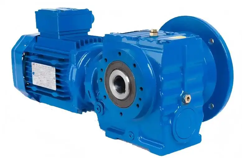
Planning a new machine layout? Send a shaft orientation sketch or a simple layout drawing showing where the motor sits and where the output needs to be. We can help confirm whether a 90-degree drive is the right structural choice — or whether an inline or parallel-shaft configuration would simplify the build.
Step 2: Compare Worm and Helical-Bevel Gear Types
Once you confirm that 90-degree transmission is necessary, the next decision is the gear type. Two dominant architectures compete in this space: worm gear and helical-bevel gear. Both achieve 90-degree power transmission, but their internal contact mechanisms are fundamentally different — and that difference drives efficiency, heat generation, ratio range, cost, and maintenance characteristics.
The Core Difference: Sliding Contact vs. Rolling Contact
Worm gear drives use a worm (a screw-like cylinder) meshing with a worm wheel (a gear with curved teeth). The contact between the worm and the wheel is predominantly sliding friction — the worm thread slides along the wheel tooth surface rather than rolling through it. This sliding contact is the root cause of several well-documented characteristics of worm gear drives: lower mechanical efficiency, higher heat generation, and the possibility (under certain conditions) of self-locking.
Helical-bevel gear drives use spiral bevel gears that mesh with rolling-dominant contact. The gear teeth engage through a combination of rolling and sliding, but the sliding component is much smaller than in worm drives. This translates to higher efficiency, lower heat generation, and smoother operation at higher speeds.
Side-by-Side Comparison
| Dimension | Worm Gear Motor | Helical-Bevel Gear Motor |
| Contact mechanism | Sliding (friction coupling) | Rolling-dominant |
| Efficiency | Lower; worm has more sliding contact and can achieve high ratios in compact arrangements. Actual efficiency depends on ratio, size, lubrication, and load | Higher; helical-bevel generally offers higher efficiency and lower heat. Actual values depend on ratio, stages, and load |
| Heat generation | Higher due to sliding friction | Lower due to rolling contact |
| Ratio range | Single-stage can reach high ratios | High ratios require multiple stages |
| Self-locking | Possible under certain conditions (see below) | Not self-locking |
| Cost | Generally lower | Generally higher |
| Noise | Low at low to moderate speeds | Low; smooth operation |
Important note on efficiency values: The efficiency figures shown above represent general trends drawn from manufacturer product data and technical literature. Actual efficiency depends on ratio, gear size, lubrication type, load level, and number of stages. Do not treat any single efficiency number as a fixed property of an entire gear type. A worm gear at 60:1 ratio will have different efficiency characteristics than the same worm gear design at 10:1. Similarly, a two-stage helical-bevel unit will have lower overall efficiency than a single-stage version.
Self-Locking: A Conditional Property, Not a Safety Feature
Worm gear drives can exhibit self-locking — the inability to be back-driven from the output side. This property is often mentioned in product literature, but it is critical to understand the conditions and limitations:
- Self-locking condition: The worm’s lead angle must be smaller than the equivalent friction angle between the worm thread and wheel tooth. This is a geometric and tribological relationship, not a guaranteed property of all worm gears.
- Efficiency trade-off: A self-locking worm gear pair operates at very low efficiency because the same friction that prevents back-driving also resists forward motion.
- Vibration and lubrication sensitivity: Vibration can temporarily reduce friction enough to release self-locking. Changes in lubricant temperature alter the friction coefficient, which can also affect the self-locking condition.
- Not a safety brake: A worm gear’s self-locking should never be used as a safety holding mechanism for loads that could cause injury or damage if they move. Safety holding functions require a purpose-designed brake or verified locking solution.

If your application needs to hold a load against back-driving, use an independent brake. The worm gear’s friction-based resistance may be sufficient for light loads under stable conditions, but it is not a substitute for a brake in safety-critical applications.
How to Choose Based on Operating Conditions
Rather than asking “which is better,” ask which gear type fits your operating profile:
- Short-duty, cost-sensitive applications (intermittent operation, moderate loads, budget constraints): A worm gear motor may be the practical choice. The lower efficiency matters less when the motor runs for minutes at a time rather than hours, and the initial cost is typically lower.
- Continuous-duty, efficiency-priority applications (long running hours, energy cost sensitivity, higher loads): A helical-bevel gear motor is usually the better fit. The higher efficiency means less energy wasted as heat, lower operating temperature, and better long-term reliability under sustained load.
- Applications that might benefit from self-locking (preventing back-driving under normal conditions, but not safety-critical): A worm gear motor’s self-locking tendency can be useful, but always pair it with an independent brake if the load poses any safety risk.
Not sure which gear type fits your application? Send your required reduction ratio, estimated output torque or load, and average operating hours per day. We can help assess whether a worm or helical-bevel architecture is the better structural match — before you commit to a specific model.
Step 3: Define Output Speed, Torque, and Service Requirements
After narrowing the gear type, the next step is quantifying what the drive needs to deliver at the output.
Output Speed and Reduction Ratio
The reduction ratio is determined by the motor’s rated speed and the required output speed:
Ratio = Motor RPM / Required Output RPM
For example, a 4-pole AC motor running at approximately 1,400 RPM driving a conveyor that needs 70 RPM output requires a ratio of about 20:1.
Keep in mind that the motor’s actual speed under load is slightly lower than the synchronous speed (slip in induction motors, or speed-torque curve effects in DC motors). Use the rated (loaded) speed for ratio calculation, not the theoretical synchronous speed.
Output Torque
The theoretical output torque can be approximated as:
Output Torque ≈ (Motor Rated Torque × Ratio) × Efficiency
This formula gives a starting estimate, but it has limits:
- Gearbox rated torque is the hard ceiling: The gearbox has a maximum rated output torque determined by its gear strength, bearing capacity, and housing design. Even if the math says the motor can deliver more torque through a high ratio, the gearbox may not be rated to transmit it.
- Motor operating point matters: The motor’s rated torque is the torque it can deliver continuously without overheating. Peak torque (during startup or overload) may be higher, but cannot be sustained. Do not use stall torque or peak torque as the basis for continuous operation.
- Efficiency is not constant: A worm gear at 60:1 ratio will have lower efficiency than the same worm gear at 10:1. Multi-stage gearboxes compound the losses. Use efficiency as a range, not a fixed multiplier.
The takeaway: Torque calculation has three ceilings — gearbox rated torque, motor thermal limit, and efficiency at your actual ratio. Any one of these can be the binding constraint. Check all three before concluding that a given ratio and motor combination will work.
Service Factor
The service factor (also called application factor or overload factor) accounts for the nature of the driven load. A uniformly loaded conveyor (steady torque, smooth starts) needs a lower service factor than a crusher or reciprocating pump (shock loads, frequent starts, reversing).
Service factor selection depends on:
- Load class: Uniform (U), moderate shock (M), heavy shock (H)
- Operating hours per day: More hours generally require a higher factor
- Start frequency: Frequent starts introduce thermal and mechanical stress
- Full-load vs. partial-load starts: Starting under full load is more demanding
Different manufacturers use different service factor tables. When comparing suppliers, ask for the specific selection table for the series you are evaluating — do not assume that a “service factor of 1.5” means the same thing across brands.
Have a load profile but not sure about torque? Send your motor rated speed and power, target output speed, and a description of the driven load (conveyor, mixer, agitator, etc.). We can help estimate the required ratio and check whether the gearbox rating matches.
Step 4: Specify the Mounting Interface
The mounting interface is where many right-angle gear motor installations run into trouble. A motor with the correct ratio and torque can still fail to install if the shaft, flange, foot, or orientation does not match the machine.
Output Shaft: Solid vs. Hollow
| Dimension | Solid Shaft | Hollow Shaft |
| Connection method | Coupling, sprocket, or pulley mounted on the shaft | Driven machine’s shaft inserts directly into the gearbox hollow bore |
| Space requirement | Needs space for coupling and shaft extension | More compact; eliminates the coupling |
| Alignment | Requires careful alignment (radial and angular) between gearbox and driven shaft | Self-aligning; the shaft enters the bore directly |
| Torque transfer | Through key and keyway on the shaft | Through flat key (DIN 6885) or shrink disc (expansion disk) |
| Disassembly | Relatively straightforward | May require hydraulic puller or specialized tooling |
| Reaction torque | Transmitted through coupling to machine frame | Requires torque arm or reaction bracket to prevent gearbox rotation |
Hollow shaft does not mean “no reaction torque management.” When a gearbox is mounted directly on the driven shaft (hollow shaft configuration), the reaction torque — the torque that tries to rotate the entire gearbox housing in the opposite direction of the output — must be absorbed by a torque arm, reaction bracket, or other mechanical link to the machine frame. Without this, the gearbox will rotate under load.
Foot Mounting vs. Flange Mounting
- Foot mounting: The gearbox sits on a base plate or machine frame, bolted through foot castings. This is the most common industrial mounting style and works well when the machine has a flat mounting surface.
- Flange mounting: The gearbox mounts to a vertical or horizontal face via a machined flange. This is common in equipment where the drive is side-mounted or where space below the drive is restricted.
- Critical rule: If a gearbox has both foot and flange mounting options, do not bolt both simultaneously. Tightening both foot bolts and flange bolts creates competing forces that can distort the housing, misalign the gears, and cause premature bearing failure. Use one mounting method per installation.
Mounting Position and Lubrication
Right-angle gear motors can be installed in different orientations — horizontal, vertical, angled — depending on the machine design. The mounting position directly affects the oil level inside the gearbox:
- Oil bath lubrication relies on the gears dipping into the oil sump. If the gearbox orientation changes, the oil level relative to the gears changes.
- Changing the mounting position from the original specification requires adjusting the oil fill quantity to ensure proper gear lubrication.
- Breather/vent position: The gearbox breather (a small vent that equalizes internal pressure) must be positioned at the highest point of the installed orientation. If the breather ends up below the oil level, oil will leak out.
- Vertical motor installation: When the motor is mounted vertically (pointing up or down), precautions are needed to prevent liquids or contaminants from entering the motor along the shaft.
Most manufacturers use a mounting position code (such as M1 through M6) as an industry convention to define the six standard installation orientations. When ordering, specify the mounting position code so the factory fills the correct oil quantity and positions the breather appropriately.
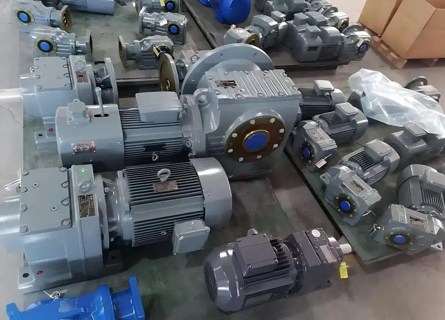
Specifying the mounting interface? Send the driven shaft diameter, keyway dimensions, and available axial length. If this is a replacement, provide photos of the existing installation — nameplate, output shaft, mounting face, and overall space — so we can confirm the correct mounting configuration before quoting.
Step 5: Evaluate Environment, Sealing, and Maintenance Access
The operating environment affects gear type selection, sealing requirements, lubrication, and long-term reliability.
Ambient Temperature
Standard industrial gear motors are typically rated for ambient temperatures of 0°C to +40°C. If your equipment operates in a colder environment (below 0°C), the lubricant viscosity at startup may be too high, causing inadequate lubrication until the oil warms up. In hotter environments (above 40°C), the gearbox’s thermal dissipation capacity is reduced, and the oil may degrade faster.
Contamination and Sealing
- Dusty environments (mining, cement, grain handling): Require robust shaft seals (lip seals, labyrinth seals, or V-rings) to prevent abrasive particles from entering the gearbox and damaging gear teeth and bearings.
- Washdown environments (food processing, pharmaceutical): Require stainless steel hardware, sealed housings, and IP-rated enclosures. Standard industrial gear motors may not be suitable without specific sealing upgrades.
- Outdoor installation: Requires protection against moisture ingress, UV degradation of non-metallic components, and temperature cycling.
Maintenance Access
Right-angle gear motors need periodic maintenance: oil checks and changes, seal inspection, and eventually bearing or gear replacement. When designing the installation, ensure there is enough clearance around the gearbox for:
- Checking and changing oil (drain plug and fill plug access)
- Inspecting the breather
- Removing the unit for service (bolt access, lifting clearance)
- Measuring temperature on the housing surface
A compact installation that saves 50 mm of machine width but blocks the oil drain plug will cost far more in maintenance downtime than it saves in space.
Step 6: Match the Motor — Voltage, Power, Brake, and Control
The final step is specifying the motor side of the gear motor assembly.
Motor Power and Voltage
- AC induction motors are the most common choice for industrial right-angle gear motors. Standard voltages (e.g., 230/400V 50Hz, 460V 60Hz) and standard frame sizes make replacement and integration straightforward.
- DC motors may be used in applications requiring speed control via voltage adjustment, battery-powered equipment, or specific OEM designs. DC gear motors have different current and control considerations (see our DC Gear Motor selection guide for details).
- Power selection: The motor power must be sufficient to drive the maximum required torque at the required speed, with the service factor applied. Undersizing the motor leads to overload and overheating; oversizing wastes energy and may increase cost unnecessarily.
Brake
If the application requires the load to stop and hold position (conveyors on inclines, vertical lifts, positioning systems), a brake is necessary. Specify:
- Brake function: Holding (maintain position when power off), stopping (decelerate the load to rest), or emergency stop
- Brake torque: Must be sufficient to hold or stop the maximum expected load
- Brake voltage: Must match the control system (AC or DC, with appropriate rectifier if needed)
- Brake type: Spring-applied (failsafe — engages when power is removed) is standard for safety applications
Do not rely on a worm gear’s self-locking as a substitute for a brake. As discussed in Step 2, self-locking is conditional and can be released by vibration or lubricant temperature changes.
Control and Feedback
If the application requires variable speed, positioning, or synchronized operation with other drives, specify the control requirements:
- Variable frequency drive (VFD) for AC motors: Allows speed adjustment, soft starting, and torque control. Ensure the gearbox is rated for the operating speed range and that low-speed cooling is adequate.
- Encoder or resolver feedback: For closed-loop speed or position control
- Reversing: If the application requires frequent direction changes, the gearbox and motor must be rated for reversing duty, and the brake (if fitted) must release quickly enough to allow smooth reversal
Selection Summary: Decision Tree and RFQ Parameters
Decision Tree
- Is 90-degree transmission required by the machine layout? → If yes, proceed. If no, consider inline or parallel-shaft.
- What gear type fits the operating profile? → Short/intermittent duty + cost priority → worm. Long/continuous duty + efficiency priority → helical-bevel.
- What ratio and output torque are needed? → Calculate from motor speed and required output speed. Check against gearbox rated torque.
- What mounting interface does the machine require? → Solid or hollow shaft, foot or flange, mounting position code, reaction torque management.
- What environment will the unit operate in? → Temperature, contamination, sealing, maintenance access.
- What motor specifications are needed? → Power, voltage, brake, control, feedback.
RFQ Parameter Checklist
When sending an inquiry to a supplier, provide as much of the following as possible:
| Category | Parameters |
| Application | Machine type, driven component, layout description |
| Output | Required output RPM, required torque or load description |
| Motor | Power (kW or HP), voltage, frequency, phase (AC) or supply voltage (DC) |
| Ratio | Target reduction ratio (if known) or motor speed for calculation |
| Duty | Operating hours/day, starts per hour, full-load or partial-load start |
| Mounting | Shaft type (solid/hollow), shaft diameter, flange or foot, mounting position |
| Environment | Ambient temperature range, contamination level, indoor/outdoor |
| Brake | Required (yes/no), function (holding/stopping/emergency), voltage |
| Control | VFD (yes/no), encoder feedback (yes/no), reversing required (yes/no) |
| Quantity | Initial order quantity and annual estimate |
Ready to get a specific model recommendation? Upload your machine layout sketch or existing nameplate data along with the parameters above. We will review the shaft orientation, gear type suitability, mounting configuration, and duty requirements, then confirm a series and model combination that fits your equipment.
Share on Social:


Contact Us
In This Article
Right Angle Geared Motor: Matching Electrical Supply, Variable Speed and Braking
Oct 26, 2026
Planning a Bevel Reducer Installation: Turn Shaft Requirements Into a Practical Drive Layout
Oct 26, 2026
Choosing an Overhead Crane Gearbox by Its Hoisting or Travel Function
Oct 26, 2026
Replacing an Industrial Worm Gearbox: What to Keep and What to Reassess
Oct 25, 2026