


 Home /
Geared Motors Efficiency: Motor vs. Gearbox vs. System Losses

Right Angle Geared Motor: Matching Electrical Supply, Variable Speed and Braking
Oct 26, 2026

Planning a Bevel Reducer Installation: Turn Shaft Requirements Into a Practical Drive Layout
Oct 26, 2026

Choosing an Overhead Crane Gearbox by Its Hoisting or Travel Function
Oct 26, 2026

Replacing an Industrial Worm Gearbox: What to Keep and What to Reassess
Oct 25, 2026
A high-efficiency motor does not automatically create high-efficiency Geared Motors.
In a real drive system, electrical power passes through the inverter, motor, gear mesh, bearings, seals and lubricant before useful torque reaches the machine. For OEM engineers and plant operators, the relevant question is therefore not simply "Is the motor IE4?" but:
How much input power is required to deliver the specified torque and speed at the gearbox output shaft?
From Mingye's engineering perspective, efficient Geared Motors start with the complete torque-speed-load relationship rather than the motor nameplate alone.
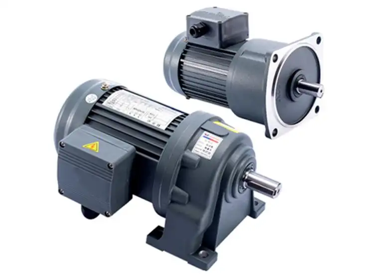
Why Motor Efficiency Is Only One Part of Geared Motors Efficiency
The power path can be simplified as:
Electrical Input → VFD → Motor → Gearbox → Output Shaft
Each stage introduces losses.
Motor Losses
An AC motor loses energy through:
• Stator and rotor copper losses
• Core or iron losses
• Bearing and fan losses
• Stray-load losses
IEC 60034-30-1:2025 classifies applicable motors by IE efficiency level and now includes IE5. Importantly, the standard also states that power-drive-system losses, including converters, cables and filters, are outside the motor IE classification. Geared motors are covered where the motor falls within the standard's scope.
Gearbox Losses
Once power enters the gearbox, additional losses occur through:
• Tooth sliding and rolling friction
• Bearing friction
• Seal drag
• Oil churning
• Multiple gear meshes
• Misalignment or incorrect preload
This is why Geared Motors with identical motor ratings can produce different input-power requirements and operating temperatures.
Motor, Gearbox and System Efficiency Must Be Separated
A useful simplified relationship is:
ηsystem = ηdrive × ηmotor × ηgearbox
Consider an illustrative operating point:
• VFD efficiency: 98%
• Motor efficiency: 94%
• Gearbox efficiency: 96%
The resulting system efficiency is approximately 88.4%.
The 94% motor figure therefore does not represent output-shaft efficiency.
For industrial Geared Motors, buyers should always establish where an efficiency value is measured: at the electrical input, motor shaft, gearbox input or gearbox output.
Gear Geometry Changes Where Mechanical Losses Occur
Gear type affects friction mechanism, reduction capability, packaging and thermal behavior.
| Gear Arrangement | Main Efficiency Issue | Typical Engineering Reason for Selection |
| Helical | Multiple meshes in multi-stage units | Smooth continuous-duty transmission |
| Helical-bevel | Additional right-angle gear stage | Efficient 90° power transmission |
| Worm | High sliding contact | Compact high-ratio right-angle drive |
| Planetary | Multiple simultaneous meshes | High torque density in compact space |
A worm unit should not simply be labelled "inefficient," nor should a helical unit automatically be considered the best choice.
The correct comparison is based on the required:
Torque → Speed → Ratio → Mounting direction → Duty cycle → Thermal limit
Mingye's drive portfolio includes helical, worm, parallel-shaft and helical-bevel configurations, allowing Geared Motors to be selected around the machine architecture rather than forcing one transmission layout into every application.
IE3, IE4 or IE5 Cannot Correct Poor Gear Motor Sizing
Higher motor efficiency reduces electrical losses, but sizing determines where the motor actually operates on its efficiency curve.
A common problem is oversizing.
A conveyor may require only moderate running torque, yet an excessively large motor is selected for "safety." The result can be:
• Low percentage load during normal operation
• Higher initial cost
• Poorer utilization of the motor
• Larger gearbox and mounting envelope
• No guarantee of lower annual energy consumption
At Mingye, a more useful selection sequence for Geared Motors is:
Required output torque → Output RPM → Transmission ratio → Motor power → Starting condition → Duty cycle
Mechanical power can be checked using:
P (kW) = T (Nm) × n (rpm) / 9550
This prevents motor kW from becoming the only sizing criterion.
VFD-Controlled Geared Motors Need Operating-Point Analysis
A VFD adds conversion losses, so installing one does not automatically improve efficiency.
Its advantage appears when the process benefits from variable speed or reduced operating demand. IEC 61800-9-2 evaluates energy efficiency for complete drive modules and power drive systems using operating points and speed/torque profiles—not only rated conditions.
For VFD-driven Geared Motors, engineers should check:
• Minimum and maximum operating frequency
• Continuous torque at low speed
• Motor cooling below rated speed
• Required acceleration torque
• Gearbox input-speed limits
• Frequent start/stop cycles
• Actual hours at each operating point
Low-speed operation needs extra thought. Even though shaft speed is reduced, the load may still require torque. Cooling may be further restricted by the reduced airflow generated by a shaft-mounted cooling fan.
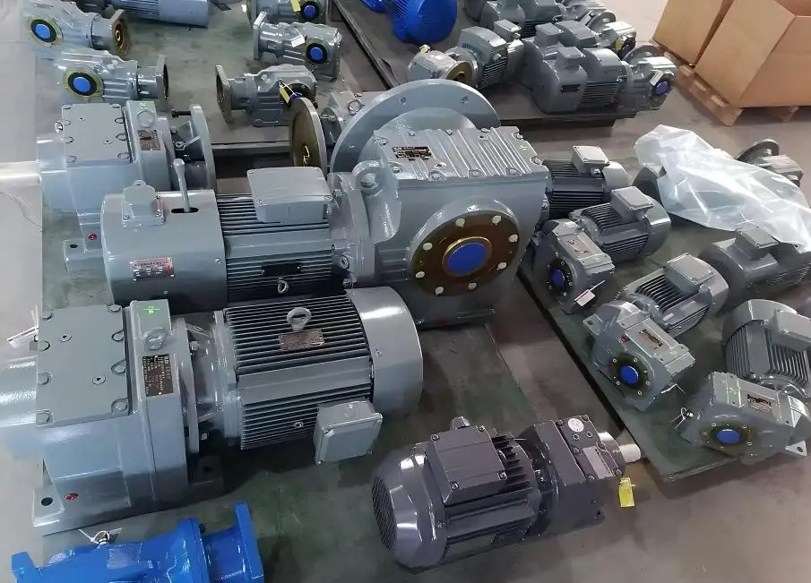
Ratio and Gear Stages Affect More Than Output RPM
Although the gear ratio affects the output shaft speed, the required total ratio may also influence how many stages are required.
More stages may result in:
• Additional gear-mesh losses
• More bearings and seals
• Greater lubricant interaction
• Increased cumulative mechanical losses
Selecting too low a ratio may result in the motor or downstream machine operating outside of the required speed-torque range.
The objective of efficient Geared Motors is not the lowest ratio and least number of stages. The objective is achieving the required output point with the most optimal design and the lowest overall losses.
Lubrication and Temperature Are Part of the Efficiency Equation
Efficiency does not remain constant throughout service life.
Oil viscosity that is too high can increase churning losses, particularly during cold starts. Poor lubrication, worn bearings or incorrect alignment can increase friction and convert useful power into heat.
A temperature increase should therefore trigger checks of:
• Actual output torque
• Oil grade and oil level
• Bearing condition
• Shaft alignment
• Seal condition
• Ventilation
• Operating speed
For Mingye, manufacturing accuracy is also part of this equation. Its production process includes CNC shaft and housing machining, gear hobbing, gear grinding and CMM inspection. These processes support controlled geometry and consistent gear engagement rather than relying only on final assembly adjustment.
How to Compare Geared Motors Before Purchasing
An efficiency percentage without its test boundary has limited procurement value.
When comparing Geared Motors, an RFQ should define:
• Required output torque and RPM
• Motor power and IE class
• Gear ratio and gear arrangement
• Continuous and peak loads
• Starts per hour
• Duty cycle
• VFD operating range
• Ambient temperature
• Mounting position
• Lubrication requirement
• Efficiency measurement point
• Expected annual operating hours
Mingye also supports modular configuration, special transmission ratios, mounting adjustments and OEM transmission solutions, which is particularly useful when standard catalog Geared Motors do not match the machine's mechanical envelope or operating point.
Select Geared Motors by Output Performance, Not One Efficiency Number
Efficient Geared Motors are the result of a matched system: motor efficiency, gear geometry, ratio, torque, speed, VFD strategy, lubrication and duty cycle all matter.
For OEMs and industrial buyers, the better comparison is usable output power, operating-point efficiency and lifecycle energy cost, not the highest efficiency figure on a single component.
Mingye provides multiple Geared Motors configurations for conveying, packaging, automation and other industrial drive applications. For a new project, you can review Mingye Geared Motors and match the drive around actual torque, speed, ratio, duty cycle and installation requirements before selecting the final configuration.
FAQs
Q1. What types of Geared Motors does Mingye provide?
Mingye provides multiple Geared Motors configurations for industrial transmission applications, including helical, worm, parallel-shaft and helical-bevel drive arrangements. Selection depends on output torque, speed, ratio, mounting space and operating duty.
Q2. How does Mingye help customers select the correct Geared Motors?
Mingye can evaluate application parameters such as required output torque, output speed, transmission ratio, motor power, duty cycle, starting load and installation arrangement before determining a suitable geared motor configuration.
Q3. Can Mingye customize the gear ratio of Geared Motors?
Yes. For applications where standard ratios do not provide the required output speed or torque, Mingye can evaluate customized transmission ratios and drive configurations according to the machine's operating requirements.
Q4. Does Mingye offer Geared Motors for VFD operation?
Mingye Geared Motors can be selected for variable-speed drive applications where appropriate. Engineers should specify the frequency range, continuous torque, minimum operating speed, acceleration requirements and duty cycle when requesting a solution.
Q5. How does Mingye control gear manufacturing accuracy?
Mingye's manufacturing capabilities include CNC machining, gear hobbing, gear grinding and dimensional inspection. Controlling shaft, housing and gear geometry helps maintain consistent gear engagement and transmission performance.
Share on Social:


Contact Us
In This Article
Right Angle Geared Motor: Matching Electrical Supply, Variable Speed and Braking
Oct 26, 2026
Planning a Bevel Reducer Installation: Turn Shaft Requirements Into a Practical Drive Layout
Oct 26, 2026
Choosing an Overhead Crane Gearbox by Its Hoisting or Travel Function
Oct 26, 2026
Replacing an Industrial Worm Gearbox: What to Keep and What to Reassess
Oct 25, 2026