


 Home /
Gear Reduction Motor Replacement: 5 Specifications You Need to Match

Right Angle Geared Motor: Matching Electrical Supply, Variable Speed and Braking
Oct 26, 2026

Planning a Bevel Reducer Installation: Turn Shaft Requirements Into a Practical Drive Layout
Oct 26, 2026

Choosing an Overhead Crane Gearbox by Its Hoisting or Travel Function
Oct 26, 2026

Replacing an Industrial Worm Gearbox: What to Keep and What to Reassess
Oct 25, 2026
A maintenance technician needs to replace a failed gear reduction motor on a production line. The nameplate is corroded but partially legible — the power and ratio are visible, but the shaft diameter and mounting type are not. The technician orders a unit with the same power and ratio. When it arrives, the output shaft is 5 mm smaller than the original, the foot bolt pattern is different, and there is no brake — the original unit had one. The machine is down for another week while the correct unit is sourced.
This scenario is common because replacement buyers often focus on the nameplate electrical data (power, voltage, ratio) and overlook the mechanical interface, brake, and mounting data that determine whether the new unit will physically fit and functionally match. This article provides a replacement checklist that covers all the data needed to order a correct replacement — regardless of whether the original is an inline, parallel-shaft, or right-angle gear reduction motor.
Step 1: Determine What Needs Replacement
Before capturing measurements, determine the scope of the replacement. Not every failure requires replacing the entire gear motor.
| Replacement Scope | When It Applies | What to Verify |
| Motor only | The gearbox is mechanically sound, but the motor has failed (electrical fault, winding burnout, bearing failure on the motor side). Initial hand checks may reveal obvious binding or roughness, but they do not establish gearbox condition. A qualified technician should determine whether the surviving component is suitable for reuse. | The replacement motor’s frame size, flange, and shaft must match the gearbox input interface |
| Gearbox only | The motor is electrically and mechanically sound, but the gearbox has failed (gear tooth damage, bearing failure, housing crack) | The replacement gearbox’s input interface must match the existing motor |
| Complete gear motor | Both motor and gearbox are failed, or the unit is obsolete and a complete replacement is more cost-effective than repair | All interface data must be captured — motor, gearbox, and mounting |
Do not assume the scope is “complete gear motor” just because the unit is old. If the motor can be repaired or replaced separately, you may save significant cost and downtime — but only if the gearbox is still serviceable. Have a qualified technician inspect both components before ordering.

Not sure whether to replace the motor, the gearbox, or the complete unit? Send a description of the failure mode (motor side or gearbox side) and whether the gearbox rotates smoothly by hand. We can help determine the replacement scope — and ensure the replacement interface matches the surviving component.
Step 2: Ask Why the Original Failed
Before ordering a replacement with the same specifications, ask: why did the original fail? If the failure was caused by an application mismatch (overload, wrong duty cycle, inadequate service factor, environmental conditions), replacing the unit with the same specification will reproduce the same failure.
Common failure causes that should change the replacement specification:
- Overload (motor drawing above rated current) → Check if load has increased; may need larger motor or different ratio
- Gear tooth failure → Check if service factor was adequate; may need larger gearbox frame size
- Overheating (continuous duty on intermittent-rated unit) → Verify actual duty cycle; may need S1-rated motor
- Bearing failure from misalignment → Fix alignment before installing replacement; check shaft and coupling dimensions
- Seal failure from contamination → Upgrade IP rating or sealing; address environmental cause
- Repeated failures of the same model → Stop ordering the same specification; submit operating conditions for re-selection
For a detailed framework on distinguishing application mismatch from manufacturing defect, see our failure analysis guide.
Step 3: Capture Nameplate Data
Start by photographing the nameplate. Even if it is corroded or partially damaged, the photo may contain enough information for a supplier to identify the series and approximate specification.
| Parameter | Why It Matters |
| Brand and model number | Identifies the series and approximate specification |
| Motor power (kW or HP) | Confirms the motor size |
| Voltage / frequency / phase | Confirms the electrical supply requirements |
| Ratio (e.g., 1:30) | Confirms the reduction ratio |
| Output speed (RPM) | Cross-checks the ratio against motor speed |
| IP rating | Confirms the sealing level |
| Insulation class (e.g., F, H) | Confirms the thermal rating |
| Duty type (if marked, e.g., S1, S3) | Confirms the duty classification |
| Brake (if indicated) | Confirms whether a brake is fitted and its voltage |
| Mounting position code (if marked) | Confirms the installation orientation |
| Manufacturing date or serial number | Helps identify the production generation |
If the nameplate is missing or unreadable, photograph the entire unit from all angles. The housing shape, bolt pattern, shaft configuration, and terminal box position may allow the supplier to identify the series.
Step 4: Capture Mechanical Interface Data
The mechanical interface data determines whether the replacement will physically fit the existing machine. This is where most replacement failures occur.
Output Shaft
| Measurement | How to Measure | Why It Matters |
| Shaft type (solid or hollow) | Visual inspection | Determines connection method |
| Shaft diameter | Caliper at the bearing journal | Must match coupling or driven shaft |
| Usable shaft length | Exposed length that engages the coupling or driven shaft | Must be long enough for full engagement |
| Keyway width | Caliper across the keyway | Must match the key |
| Keyway depth | Depth gauge from shaft surface to keyway bottom | Must match the key dimensions |
| Hollow bore diameter (if hollow) | Inside caliper or bore gauge | Must match the driven shaft diameter |
| Keyway in hollow bore (if keyed) | Width and depth | Must match driven shaft keyway |
Mounting Interface
| Measurement | How to Measure | Why It Matters |
| Mounting type (foot, flange, or both) | Visual inspection | Determines which bolt pattern to capture |
| Foot bolt pattern | Center-to-center distance of bolt holes, both directions | Must match machine base |
| Foot bolt hole diameter | Caliper measurement | Must match mounting bolts |
| Center height (foot-mounted) | Foot base to shaft centerline | Must match machine base height |
| Flange pilot diameter (flange-mounted) | Caliper measurement of the locating spigot | Must match machine face bore |
| Flange bolt circle diameter | Distance between opposite bolt holes | Must match machine face |
| Flange bolt hole count and diameter | Visual count and caliper | Must match machine face |
| Mounting position code (M1–M6) | Visual inspection of installed orientation | Determines oil fill and breather position |
Overall Envelope
| Measurement | Why It Matters |
| Total length (motor + gearbox) | Must fit within available space |
| Total width | Must clear adjacent equipment |
| Total height | Must fit under or over adjacent structures |
| Oil drain plug position | Must be accessible for oil changes |
| Oil fill/breather position | Must be accessible for filling and inspection |
Step 5: Capture Motor, Brake, and Control Data
| Parameter | What to Record | Why It Matters |
| Terminal box position | Top, left, right, bottom | Cable must reach; no structural conflict |
| Cable entry direction | Direction the cable enters the terminal box | Cable routing must work in the installation |
| Brake presence | Yes/no | Machine must hold/stop correctly |
| Brake voltage | V (AC or DC) | Must match control system |
| Brake torque (if marked) | N·m | Must be sufficient for the load |
| Rotation direction | CW or CCW (from output shaft end) | Machine must run in the correct direction |
| Encoder or feedback device | Yes/no, type | Required for closed-loop control |
| Forced cooling fan | Yes/no | Required for low-speed VFD operation |
How to determine rotation direction: If the original unit is still running, observe the output shaft and mark the direction with an arrow on the housing. If the unit is already removed, check the driven machine’s nameplate or operating manual for the required rotation direction, or check for an existing arrow marking on the housing or machine drawing.
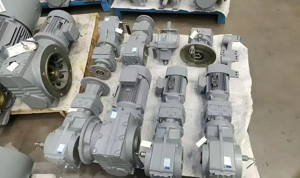
Same model failed multiple times? Stop ordering the same specification. Upload the nameplate, failure photos, and operating conditions (hours, starts, load type). We can review whether the original specification matches the actual application — and recommend a different model, ratio, or service factor if the selection was incorrect from the start.
Step 6: Capture Driven Component and Load Data
The gear motor does not exist in isolation — it drives something, and the driven component affects the replacement specification.
| Parameter | Why It Matters |
| Driven component type (coupling, sprocket, pulley, direct shaft) | Determines shaft type and connection method |
| Sprocket/pulley pitch diameter | Affects overhung load calculation |
| Chain/belt tension | Affects overhung load and bearing life |
| Coupling type and size | Must match the new shaft dimensions |
| Driven shaft diameter and length (for hollow shaft) | Must match the new hollow bore |
| Load type (uniform, moderate shock, heavy shock) | Affects service factor verification |
| Operating hours per day | Affects duty type verification |
| Starts per hour | Affects duty type and service factor |
Replacement Photo Checklist
Capture the following photos before contacting a supplier. (If your unit is a right-angle gear motor, also see our right-angle replacement guide for additional orientation and handing photos.)
- Nameplate — Close-up, legible photo of the entire nameplate
- Output shaft — Photo showing the shaft end, keyway, and diameter (with a ruler or caliper in the frame for scale)
- Mounting face or foot — Photo showing the bolt pattern and pilot (if flange) or foot configuration
- Overall installation — Wide shot showing the entire gear motor in position, with motor, gearbox, driven shaft, and adjacent equipment visible
- Terminal box and cable entry — Photo showing where the power cable enters the motor
- Brake (if fitted) — Photo showing the brake unit and its position on the motor
If the nameplate is completely unreadable: Photograph the housing from all four sides. The housing shape, bolt pattern, shaft exit position, and terminal box location may allow the supplier to identify the series. Also photograph any casting numbers or partial markings on the housing.
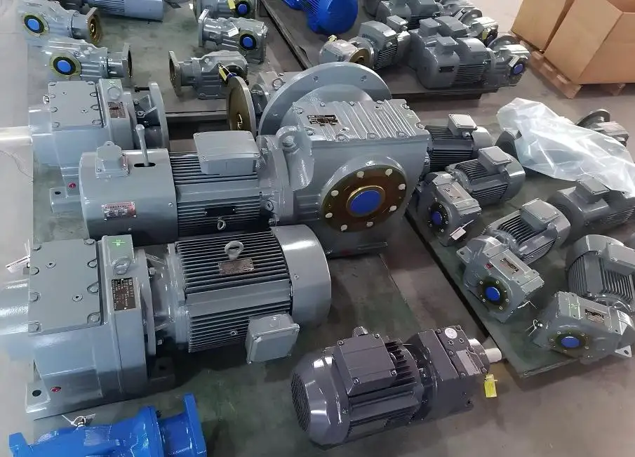
Replacement Measurement Template
This template covers all gear reduction motor types. If your unit is a right-angle gear motor, also capture the orientation and handing data described in our right-angle replacement guide. Copy this template, fill in the measurements, and send it with the photos:
REPLACEMENT INQUIRY — Gear Reduction Motor
SCOPE:
Replacement scope: Motor only / Gearbox only / Complete gear motor
Reason for replacement: _______________
Failure mode: _______________
Has this model failed before in this application? Yes / No
NAMEPLATE DATA:
Brand/Model: _______________
Motor Power: _______________ kW
Voltage: _______________ V
Frequency: _______________ Hz
Phase: _______________
Ratio: 1:_______________
Output Speed: _______________ RPM
IP Rating: _______________
Insulation Class: _______________
Duty Type (if marked): _______________
Brake: Yes / No (if yes, voltage: _______________ V)
Mounting Position Code (if known): _______________
OUTPUT SHAFT:
Type: Solid / Hollow
Diameter: _______________ mm
Usable Length: _______________ mm
Keyway Width: _______________ mm
Keyway Depth: _______________ mm
Hollow Bore Diameter (if hollow): _______________ mm
MOUNTING:
Type: Foot / Flange / Both (specify which is used)
Foot Bolt Pattern: _______________ mm x _______________ mm
Foot Bolt Hole Diameter: _______________ mm
Center Height: _______________ mm
Flange Pilot Diameter: _______________ mm
Flange Bolt Circle Diameter: _______________ mm
Flange Bolt Hole Count: _______________
MOTOR/BRAKE/CONTROL:
Terminal Box Position: Top / Left / Right / Bottom
Cable Entry Direction: _______________
Brake: Yes / No (voltage: _______________ V)
Rotation Direction: CW / CCW (from output shaft end)
Encoder: Yes / No
Forced Cooling Fan: Yes / No
DIMENSIONS:
Total Length: _______________ mm
Total Width: _______________ mm
Total Height: _______________ mm
DRIVEN COMPONENT:
Type: Coupling / Sprocket / Pulley / Direct Shaft
Sprocket/Pulley Pitch Diameter: _______________ mm
Driven Shaft Diameter (for hollow shaft): _______________ mm
OPERATING CONDITIONS:
Hours per Day: _______________
Starts per Hour: _______________
Full-Load Start: Yes / No
Reversing: Yes / No
Ambient Temperature: _______________ °C
Load Type: Uniform / Moderate Shock / Heavy Shock
If the Original Brand Is Discontinued
If the original gear motor brand is no longer available, or the specific model has been discontinued, the replacement becomes a reverse-engineering exercise. The nameplate data and measurements above become the specification for finding an equivalent unit from a different manufacturer.
Prioritize the parameters that cannot be adapted — these must match exactly:
- Output shaft diameter and keyway — machining a new shaft or coupling is costly
- Mounting bolt pattern and center height — modifying the machine base is expensive
- Rotation direction — cannot be changed without redesigning the drive layout
- Mounting position code — determines lubrication; wrong orientation means oil level issues
Parameters that can be adapted with reasonable effort:
- Housing dimensions — a slightly different footprint can be accommodated with an adapter plate
- Coupling type/size — couplings are standard components that can be replaced
- Terminal box position — cable routing can often be adjusted
- Oil fill quantity — adjusted based on the new mounting position code
The one-line rule: If modifying the parameter requires changing the machine base or driven shaft, it must match exactly. If it can be accommodated with an adapter, spacer, or cable adjustment, it can be adapted.
The supplier should perform an interchangeability check — comparing the original unit’s specifications against available alternatives — and identify any differences before shipping, not after the unit arrives on site.
Replacing a gear reduction motor? Do not guess the model — photograph first. Send photos of the nameplate, output shaft (with a ruler for scale), mounting face or foot, and the overall installation space. We can identify the series, confirm the shaft and mounting dimensions, and check whether a direct replacement is available — or whether the dimensions require a modified mounting approach.
Share on Social:


Contact Us
In This Article
Right Angle Geared Motor: Matching Electrical Supply, Variable Speed and Braking
Oct 26, 2026
Planning a Bevel Reducer Installation: Turn Shaft Requirements Into a Practical Drive Layout
Oct 26, 2026
Choosing an Overhead Crane Gearbox by Its Hoisting or Travel Function
Oct 26, 2026
Replacing an Industrial Worm Gearbox: What to Keep and What to Reassess
Oct 25, 2026