


 Home /
 Vibration and Noise Control: How a Cycloidal Reducer Achieves Smooth Operation
Gear Motor Factory With Modular Design For Easy System Integration
Jun 19, 2026
From Input to Output: A Step-by-Step Look at the Ball Mill Gearbox Power Transmission Path
Jun 18, 2026
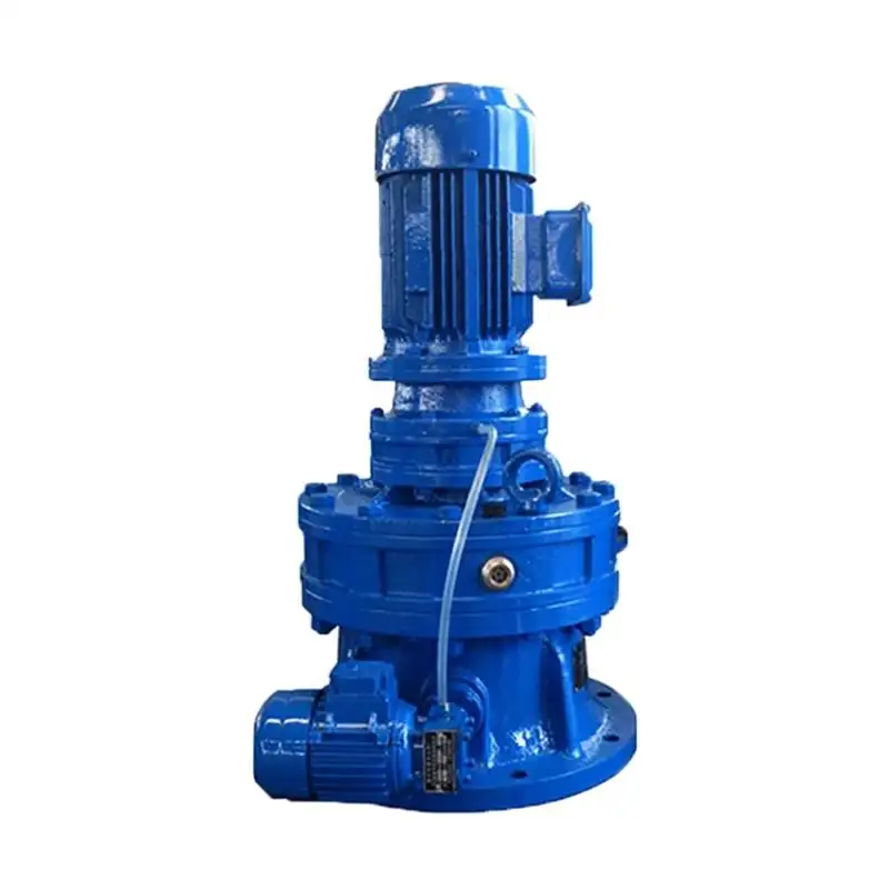
Vibration and Noise Control: How a Cycloidal Reducer Achieves Smooth Operation
Jun 17, 2026
How a Planetary Gearbox Achieves High Load Capacity – Dual Bearing & Needle Roller Secrets
Jun 16, 2026
The modern workplace demands optimal efficiency from every mechanical system in the factory. Not meeting that demand results in a loss of profit from transferring energy into motion. An example of a loss from motion energy transfer is excessive noise and vibration. As mechanical systems wear, mechanical noise and vibration increase. This article identifies the problems of mechanical noise and mechanical vibration and explains how the specific design of a cycloidal pinwheel reducer alleviates those issues.
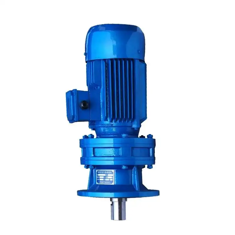
Understanding Mechanical Noise and Vibration in Gear Reducers
Every problem has a solution, so examining the solution requires an understanding of the problem first. Modern gear reducers use either spur gears or helical gears. Both spur and helical gear reducers experience mechanical noise and vibration from:
•The friction of sliding teeth. As a spur gear turns, its teeth slide over their counterparts, creating an interrupted engagement that increases the friction between the sliding teeth and generates a high frequency noise and vibration.
•The periodic errors in gear alignment from the manufacturing tolerances and elastic deformation of a gear.
•Mechanical noise and vibration limit the efficiency of modern mechanical systems.
The Difference of a Cycloidal Reducer
The fundamental operating principle of a cycloidal pinwheel reducer is different than spur and helical gear reducers. Heavily reliant on an eccentric motion system and differential tooth engagement mechanism, a cycloidal pinwheel reducer design is a natural vibration and noise dampener.
1. Eccentric Motion Fosters Rapid Gear Engagement
A double eccentric sleeve (of 180° phase shift) is fitted on the input shaft of the cycloidal pinwheel reducer. With the shaft, the eccentric sleeve orbits the two cycloidal discs, causing their motion to be orbital.
•Progressive contact pattern: The discs slowly meet the stationary pins on the pinwheel, rather than jarring between each other.
•Continuous rolling action: The discs roll rather than slide. This design contrasts with involute gears and with the discs rolling, the hammering effect is eliminated.
•Balanced inertia forces: With the 180° double eccentric design, the effects of the centrifugal forces are eliminated with reduced vibrations transmitted to the input.
2. Differential Tooth Meshing Enables Large Reduction Ratios per Stage
One of the highest reduction ratios, 1:11 to 1:87, is possible through cycloidal reducers with Differential Meshing, within just a single stage. This contrasts the increased number of stages in a conventional gearbox which has additional pairs of gears and bearing assemblies, and additional sources of vibration.
•Reduced number of components: The single-stage cycloidal pinwheel reducer replaces a long and complex multi-stage gear train, mechanical complexity is greatly reduced and noise is eliminated.
•Reduced error accumulation: Fewer parts mean reduced cumulative tolerances which supports improved overall output rotation.
3. Multiple Linear Contacts Offer Improved Load Distribution
Standard gears allow a maximum contact of 2 teeth, while a cycloidal pinwheel reducer allows contact with between 30 and 40% of the pinwheel teeth.
•With so many contact points load is evenly spread across many areas which eliminates micro-vibratility and pitting.
•Smooth torque output and reduced load: With altered input conditions, outputs remain stable and torque is evenly delivered.
•Less elastic deformation: A reduction in per-tooth force leads to a lack of (negligible) cycloidal disc and pin deflection when compared to higher levels of force, creating position errors and vibration.
4. Rolling Contact Decreases Internal Friction
When cycloidal discs and the pins of a pinwheel ring touch, they predominantly roll rather than slide. In fact, the majority of pins employ a needle sleeve (a rotating cylindrical element) that converts sliding friction to rolling friction.
•Lower friction: Compared with sliding friction of engaging gear teeth, rolling contact produces much less heat and greatly reduces high frequency vibrations.
•Negligible wear: Rolling contact maintains the integrity of the surface for long periods of time and, therefore, prevents the noise from increasing over time.
•Retention of lubrication films: Because rolling contact maintains mechanical vibrations of low amplitude it preserves an oil film.
5. Enclosed System with Fixed Lubrication
The complete enclosure of the cycloidal pinwheel reducer provides protection and dampens vibrations.
•Consistent lubrication: An oil bath or forced lubrication keeps all of the moving surfaces sufficiently separated, preventing metal-to-metal contact during starting or overload.
•Vibration damping: the structure and bulk of the housing and oil absorb high frequency mechanical vibrations.
•Stable operation: A controlled operating temperature of the oil viscosity prevents lubrication and friction from locking up and causing excessive vibrations.
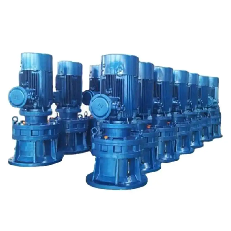
Mingye Machinery's BLD Series Cycloidal Pinwheel Reducer
The BLD Series Cycloidal Pinwheel Reducer from Mingye Machinery implements all the aforementioned features along with other engineering designs that facilitate the smoothness of operation.
1. Precision Controlled Double Eccentric Sleeve
•Balancing: The dynamic double balancing of the 180 degree sleeve eliminates the majority of unbalance at higher input speeds.
•Reduced vibration: The presence of two ball bearings on the sleeve maintains concentricity and thus reduces the radial runout which in turn decreases the vibration of the output shaft.
2. Optimized Cycloidal Disc Profile
•Proprietary tooth curve refinement: Disc tooth profiles are optimized mathematically to maintain almost constant angular velocity throughout the entire meshing cycle. This eliminates "ripple" torque.
•Surface finishing: A surface roughness of Ra ≤ 0.4 μm is achievable with precision grinding. This minimizes micro-slip and the high-frequency noise that accompanies it.
3. Robust Pinwheel Ring with Needle Rollers
•Needle pin design: The use of free-rotating needle rollers in place of fixed pins in the pinwheel ring design also further minimizes both friction and vibration by converting sliding motion into rolling.
•Case-hardened material: The pins, which are hardened, ground and case finished, will maintain their shape and minimize wear for decades of low noise cyclic operation.
4. W Output Mechanism for Smooth Low-Speed Transmission
•Balanced output structure: The W mechanism consists of a set of flange pins that transfers the motion of the cycloidal discs to the output shaft and balances forces to avoid lateral friction and vibration.
•Zero-backlash coupling: The output pins have a controlled clearance to the bushings, thus minimizing the impact of a change in motion direction.
5. Verified Industrial Performance
The BLD Series reducers have been continuously operational and field tested in a variety of applications.
•Mining & heavy industry: The BLD Series operates beside crushers and feeders with a housing vibration level that is 30–50% lower than conventional gearboxes.
•Rubber & plastic machinery: BLD cycloidal pinwheel reducers equipped extruders have less torque ripple, which leads to more uniform products.
•Material handling systems: Conveyor systems experience fewer start-up shocks which leads to less product spillage and less conveyor belt misalignment.
Practical Consequences of Noise and Vibration Reduction
The low-vibration cycloidal reducer offers quantifiable benefits to engineers and plant managers alike:
•Longer machine life: Unplanned downtime is lessened thanks to reduced stress on bearings, seals, and associated machinery.
•Greater precision: Smooth drive results in better repeatability and ultimately an improved quality of product.
•Lower noise exposure: Operations become quieter both improving the work environment and helping to satisfy occupational noise exposure limits.
•Lower foundation isolation costs: Lower drive system vibration means easier, simpler drive system mounting, which results in reduced overall costs.
Conclusion
The presence of mechanical noise and vibration in gear drives is the result of design selections, and are not a necessity. The BLD Series of the Mingye Machinery cycloidal pinwheel reducers is one example of a design that uses sound science to create an alternate solution. The design of the reducer creates smooth and reliable operation, even when under continuous and variable loads, by using eccentric rolling to replace jarring tooth engagement, active load sharing with many contact points, and an enclosure that incorporates controlled lubrication.
Long-term benefits are obvious when considering a high torque cycloidal gearbox for an industrial extruder, or cycloidal pinwheel reducers for high ratio, heavy duty, gear driven conveyors. When noise and motion stability are important factors, the BLD Series reduces vibration and is a proven effective design.
FAQs
Q1: In what ways is a cycloidal reducer superior to a conventional gear box in terms of smooth operation?
A: Cycloidal reducers feature many-to-many tooth engagement which results in multi-point rolling contact, whereas conventional gear boxes have single-point contact which results in sliding friction.
Q2: Does lower vibration in a cycloidal reducer lead to reduced wear on connected equipment?
A: Lower vibration reduces the cyclical loading and wear on bearings, seals, and driven equipment.
Q3: Was the cycloidal pin wheel reducer designed to accommodate high input speeds?
A: Not really, this type of reducer is designed for low input speeds. High input speeds may require special lubrication and are likely to require a balance check.
Q4: In what way does noise reducer housing help in controlling noise?
A: Noise reducer housing helps dampen sound and provides stable oil lubrication which reduces mechanical excitation.
Q5: What is the ideal practice to maintain low vibration over long time of use?
A: The ideal practice is to keep the reducer housing sealed to prevent contamination of the cycloidal discs and pins, and to do regular maintenance on the oil.
Share on Social:


Contact Us
In This Article
Gear Motor Factory With Modular Design For Easy System Integration
Jun 19, 2026
From Input to Output: A Step-by-Step Look at the Ball Mill Gearbox Power Transmission Path
Jun 18, 2026
Vibration and Noise Control: How a Cycloidal Reducer Achieves Smooth Operation
Jun 17, 2026
How a Planetary Gearbox Achieves High Load Capacity – Dual Bearing & Needle Roller Secrets
Jun 16, 2026