


 Home /
 From Input to Output: A Step-by-Step Look at the Ball Mill Gearbox Power Transmission Path
Gear Motor Factory With Modular Design For Easy System Integration
Jun 19, 2026
From Input to Output: A Step-by-Step Look at the Ball Mill Gearbox Power Transmission Path
Jun 18, 2026
Vibration and Noise Control: How a Cycloidal Reducer Achieves Smooth Operation
Jun 17, 2026
How a Planetary Gearbox Achieves High Load Capacity – Dual Bearing & Needle Roller Secrets
Jun 16, 2026
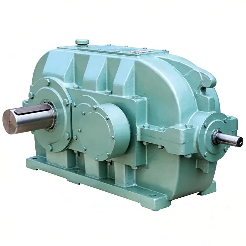
Interpreting how high-speed input from a motor is turned into low-speed, high-torque output in a ball mill gearbox is important for specialists in fields like mineral processing, production of cement, and industrial grinding. We offer a step-by-step guide on the entire energy transmission path, from the motor shaft to the mill's pinion. We define the purpose of each element, and show how some of the recent designs, exemplified by the DCY Series Cylindrical Gear Reducer developed by Mingye Machinery, help improve design reliability and efficiency.
1. Importance of the Ball Mill Gearbox in Grinding Operations
The ball mill is a major consumer of torque. Without a skilled design, the motor for the mill is bound to either burn out or stall. The gearbox has three main functions:
1.Reduction of speed from 1,000-1,500 rpm of the motor to the operational speed of the mill of about 15-20 rpm.
2.The multiplication of torque, proportional to the reduction ratio of the speed.
3.Stabilization of the load, smoothing shock loads from the grinding media.
The DCY series from Mingye Machinery is a good example of a design that incorporates all of the above features. The design uses case-hardened teeth of a helical design of a gear that has an HRC rating of 58-62 and offers modularity.
2. The Input Shaft and First-Stage Gearing
The first step of the transmission of power is the input shaft that connects directly to the motor. The first step of gear reduction is accomplishable when the rotational power of the motor is transmitted to the first pair of gears. In the DCY series, the first step of gearing may involve the use of Gleason spiral bevels (for right-angle input) or helical gears (for inline).
•First stage of a gear train (spiral bevel gears): these reduce speed and, at the same time, rotate the shaft at 90°, achieving a compact layout of the drive.
•Helical gear engagement: Teeth are engaged at an angle so that the teeth come together slowly, thus dispersing the load over a larger surface area. This lessens both the vibration and noise in comparison with straight cut gears.
•Hardened tooth surface (HRC 58–62): Mingye incorporates carburizing, hardening, and CNC grinding to first stage gears so that they will resist pitting and wear with repeated start/stop operations.
At this stage, speed reduction of about 2:1 to 5:1 is achieved, and the torque increase is in proportion.
3. Multi Stage Helical Cylindrical Gears - the Main Torque Multiplication Mechanism
Indeed, ball mill gearboxes often have multi-stage gearing. To reach high reduction ratios e.g. 31.5:1, 40:1, 50:1 for DCY series, two, three, or four stages are often used.
Second and third stages (Involute helical cylindrical gears):
•After Power transmission first stage, it is done by parallel shafts of external engagement of involute helical gears. Each stage progressively reduces speed and increases torque.
•Parallel shaft layout: Ensures that the input and output shafts are parallel, and makes alignment with the mill's pinion bearing easier.
•Gradual load distribution: Due to the fact that the teeth are engaged at an angle, each gear set instantaneously loads and, consequently, avoids the concentration of stress and prolongs the life of the bearings.
•Stage flexibility: Mingye has two-stage (B), three-stage (C), and four-stage (F) configurations so that designers can tailor the exact reduction ratio to the grinding curve of the mill.
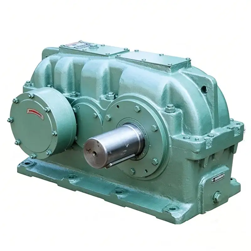
The ball mill gearbox uses a stage design that allows it to distribute the large amount of rotational power entering the first stage. It allows the gearbox to reduce power smoothly through multiple stages in a way that distributes and absorbs high impact shock loads.
4. Hardened Gear Surfaces: Why HRC 58-62 for Continuous Grinding?
Milling, at times, can be a continuous process. This means that the ball mill itself is grinding for days, months, and even years without a stopping. This can cause the teeth of the gears to micro pit and eventually cause them to break down. Mingye Machinery uses advanced material science and gear design to solve this issue.
Gear material and treatment:
•High strength low carbon alloy steel → Carburizing → Quenching → CNC profile grinding.
•Impact lands and cracking can initiate from the roughness of gear surfaces. Quenching and Carburizing allow the toughness of the core to remain while protecting impact lands from cracking.
•A CNC ground finish allows the surface to be significantly refined with a surface roughness of Ra ≤ 0.8 μm. This also aids in the grinding process by serving to reduce friction which in turn allows film lubrication to better adhere.
•Tooth hardness HRC 58–62: Provides excellent resistance to abrasive wear from contaminated lubricant—a common issue in dusty mine environments.
Thanks to this hardness, Mingye's DCY series offers "long service life" as a stated advantage, directly reducing replacement frequency and downtime.
5. Lubrication Path: Keeping the Energy Flow Cool and Clean
Power transmission generates heat, especially at high torque levels. A lubrication system is critical for productivity and avoiding severe damage.
With regards to lubrication in gearboxes of ball mills, Mingye gearboxes provides three options, based on thermal loads:
•Splash lubrication (standard) - this is appropriate at moderate speeds and power. In this method, the meshing of the gears happens in an oil sump, and oil is splashed on the bearings.
•Circulating oil system (high loads) - in this system of lubrication, oil is thermally unloaded by being cooled and filtered, and it is sprayed on the gear meshes.
•Oil-pool with cooling pipe (very high loads) - in this system, the viscosity is controlled by using a water-cooled pipe in the oil sump, when either the ambient or operating temperatures are high.
•Housing design - the dust proof, moisture proof housing, provides oil passage ways, and allows easy access for inspection of internal components of the housing, through removable covers.
•Temperature control - keeping oil below 80 degrees Celsius avoids rapid oxidation, and helps maintain a strong elastohydrodynamic film of oil on gear teeth.
6. Output Shaft and Pinion: Sending Torque to the Mill
Power passes through all of the reduction stages to reach the output shaft. This shaft connects—often via a flexible coupling—to the mill's pinion shaft, which turns the girth gear attached to the mill shell.
Final torque delivery:
•The output shaft rotates slowly (e.g., 18–22 rpm) but with very high torque (hundreds of kNm). This torque is what lifts and cascades the grinding balls inside the mill.
•Modular output configuration: Mingye offers seven assembly forms (e.g., foot-mounted, flange-mounted, hollow shaft with torque arm) to fit different mill layouts.
•Hollow output shaft option (K code): Allows direct mounting onto the mill's input shaft, eliminating a coupling and saving axial space.
•Rotation Direction Options: Mill Direction requirements are fulfilled with both clockwise and counter-clockwise options.
•The energy path is complete. Electrical energy from the motor is now fully converted into mechanical torque for grinding the ore at optimum speed and in the correct direction.
7. Real Life Advantages of Mingye's DCY Series in Ball Mill Systems
Durability, serviceability, and flexibility impact the total cost of ownership of a ball mill gearbox and the DCY series from Mingye is exceptional in all areas.
Here are some of the engineering merits:
•Enhanced load capability: Peak torque spikes can now be absorbed by the multi-stage helical gears without the chance of damage because of case hardening.
•Reduced noise and vibration: Spacing and profile adjustments of the gears can render sound pressure levels to be below 85 dB (A) at the rating load.
•Reduced housing size: Minimal weight and size of the gear assembly due to a modular stage design.
•Easy Removal and Maintenance:: Because of the split housing and bolted cover, the complete assembly removal is not required.
•Optional Stages and Hardness: 2, 3, and 4 stage gearboxes are available with teeth of either hard (Y) or medium (Z) hardness.
•Flexible assembly forms and rotation directions: 7 forms of assembly and 2 rotation directions can fit any drive configuration of a ball mill, be it central drive, edge drive, or dual pinion.
Conclusion
The high-speed input and high-torque output configuration of a ball mill gearbox illustrates how different configurations of helical and occasionally bevel gears can be designed to transmit energy along a specific path. From the first stage hardened gears to the output shaft, each element must work together to provide uninterrupted grinding. Mingye Machinery's DCY Series Cylindrical Gear Reducer highlights best practices such as use of carburized and ground (HRC 58-62), multi-stage, flexible, modular, and well designed components and/or assemblies that provide great lubrication. Knowledge of the power path will allow you to accurately specify a gearbox that will operate for years on end, whether you're designing from scratch or retrofitting a circuit.
Want something special for your ball mill? Mingye Machinery has the engineers and the will to provide a free quote based on your unique reduction and mounting requirements.
FAQs
Q1: What does the gearbox in a ball mill do?
It transmits motor power to the mill pinion at a reduced speed and multiplied torque.
Q2: What is the reason for multi-stage gearing in a ball mill?
To achieve high reduction ratios such as 31.5:1 to 50:1 to allow the mill to operate at the slow speeds necessary.
Q3: What gears are in the DCY series?
It contains external meshing involute helical gears, while the first stage may contain Gleason spiral bevel gears.
Q4: What are the lubrication methods for ball mill gearboxes?
The standard method is splash oil, while forced circulation oil, or oil-pool with cooling pipes may be used in high load or high temperature situations.
Q5: Can the DCY gearbox be mounted in different orientations?
Yes, it provides support for seven assembly forms to accommodate different arrangements of the ball mill and space availability.
Share on Social:


Contact Us
In This Article
Gear Motor Factory With Modular Design For Easy System Integration
Jun 19, 2026
From Input to Output: A Step-by-Step Look at the Ball Mill Gearbox Power Transmission Path
Jun 18, 2026
Vibration and Noise Control: How a Cycloidal Reducer Achieves Smooth Operation
Jun 17, 2026
How a Planetary Gearbox Achieves High Load Capacity – Dual Bearing & Needle Roller Secrets
Jun 16, 2026