


 Home /
Two-Roll Rubber Mill Friction Ratio: Check the Actual Drive Layout
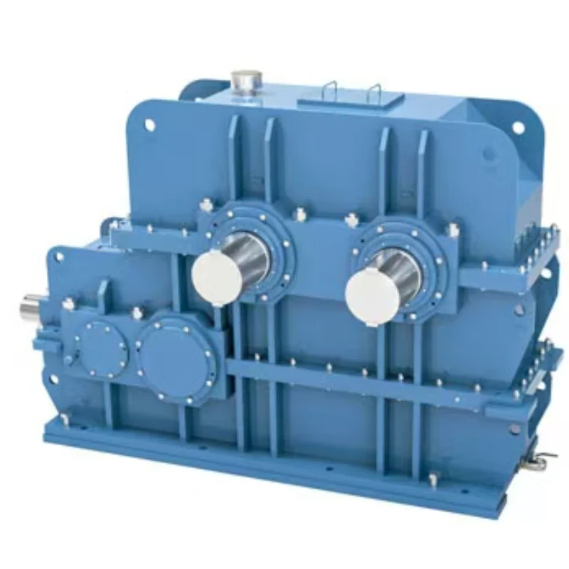
Rubber Internal Mixer Gearbox: Read the Batch Load Profile, Not Just Motor kW
Oct 22, 2026
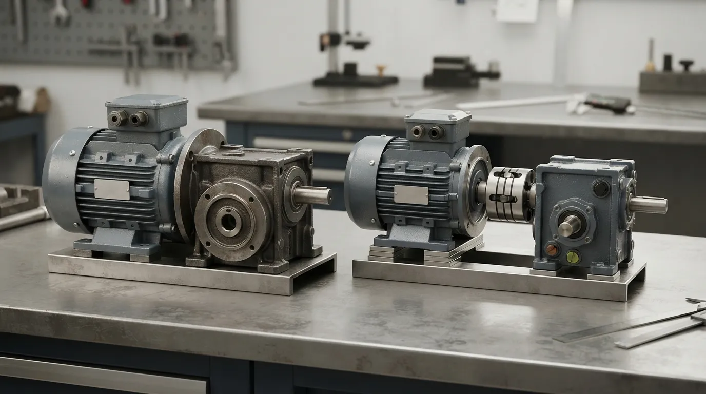
Hot Industrial Gearbox Coupling After Cold Alignment: What to Check
Oct 22, 2026
Hydraulic Slewing Drive Won't Rotate: Separate Motor, Brake and Gearbox Faults
Oct 22, 2026
Calender Roll Gap Changes: What Must the Drive Coupling Accommodate?
Oct 22, 2026
A mill rebuild commonly starts with a request for a replacement reducer. The mill has been running for years with a slightly uneven sheet and a band of uncut material along one edge, the original friction ratio was set at something like 1.35:1 on the drawing, and the assumption is that a new gearbox will restore it. The ratio and the symptoms here are placeholders for the construction, not a record of a particular mill.
In that situation the reducer being replaced may have nothing to do with the friction ratio, and working out whether it does takes one calculation and one look at the drive layout.
Working through why takes one calculation, one look at the drive layout, and one honest answer about what changes when a roll is reground. The result is a cleaner way to write a mill drive specification.
Start With the Ratio You Actually Care About
Friction ratio on a two-roll mill is defined by surface speed, not by shaft speed. What the compound experiences in the nip is the relative velocity of the two roll surfaces where they meet. That is the quantity that produces shear, and shear is the reason the mill works at all.
The relationship is simple enough to write in one line. Surface speed at the roll face is
*v* = π × *D* × *n*
where *D* is the roll diameter and *n* is the rotational speed. The friction ratio is therefore
*v*fast / *v*slow = (*D*fast × *n*fast) / (*D*slow × *n*slow)
Now look at the structure of that expression. If the two rolls have the same diameter, the diameters cancel and the friction ratio reduces to the ratio of rotational speeds. That is the case in most production mills, and it is why the two numbers are so often used interchangeably in the shop.
The cancellation is a coincidence of geometry, not a general truth. The moment the diameters differ, it stops holding.
A worked example on equal rolls
Take a mill with two 400 mm rolls. The fast roll turns at 24 rpm, the slow roll at 17.85 rpm.
- *n* ratio: 24 / 17.85 = 1.344
- Surface speed, fast roll: π × 0.400 × 24 = 30.16 m/min
- Surface speed, slow roll: π × 0.400 × 17.85 = 22.43 m/min
- *v* ratio: 30.16 / 22.43 = 1.345
The two ratios agree to within rounding. On this machine, the nameplate's 1.35:1 describes both the speed ratio and the friction ratio, and an operator can check the friction ratio with a tachometer and a calculator.
The same mill after one roll is reground
Now regrind the fast roll down to 392 mm. The 8 mm is a demonstration figure chosen to make the arithmetic visible, not a standard cut; how much comes off in practice depends on how far the surface is worn and on the roll's minimum permissible diameter. The shaft speed is unchanged, because the shafts, gears, and reducer are unchanged.
- Surface speed, fast roll: π × 0.392 × 24 = 29.56 m/min
- Surface speed, slow roll: π × 0.400 × 17.85 = 22.43 m/min
- *v* ratio: 29.56 / 22.43 = 1.318
The speed ratio is still 1.344. The friction ratio is now 1.318. The compound sees about 2 percent less relative velocity than it did before, and nobody changed a single gear.
That 2 percent is small, and on its own it does not explain a mill that stops working. But it demonstrates the principle, and the principle scales. Regrind both rolls by different amounts, or replace one roll with a spare that came from a different machine, and the drift gets larger. A mill that has been rebuilt twice often has a friction ratio that no longer matches the drawing, and no component in the drive is at fault.
Where the Two Speeds Actually Come From
Here is the part that most often gets mislaid when someone goes shopping for a reducer. On one very common mill layout, the friction ratio is not produced by the main reducer. It is produced downstream of it. That is one arrangement rather than a universal one, and the exceptions are not footnotes: a built-in differential two-output reducer, or two rolls driven independently by separate motors, establishes the ratio relationship inside the drive itself, and in those machines the friction ratio genuinely is part of the drive's responsibility. Which arrangement a given mill has is a question for its drawings, and the answer changes what the drive quotation has to cover.
What follows describes the first arrangement, because it is the one where the confusion is most costly.
The motor couples to the main reducer. The reducer's output shaft carries a small sprocket. That sprocket drives a chain to a large sprocket on the rear roll. So far the rear roll's speed is set by motor speed divided by the reducer ratio, then by the chain ratio.
Then the power crosses to the front roll. At the far end of the rear roll there is a pair of gears, one on each roll shaft, meshing with each other. These are the ratio gears. They set the front roll's speed relative to the rear roll, and because they are a gear pair with fixed tooth counts, that relative speed is fixed by machining, not by adjustment.
Read the consequences off that layout.
The reducer sets the roll speed level. Change the reducer ratio and both rolls speed up or slow down together. The mill runs faster or slower overall.
The ratio gears set the difference between the rolls. Change the tooth counts and the friction ratio changes. The overall speed level may barely move.
These are two independent functions performed by two different components. A quotation for a main reducer is a quotation for the first of them. It cannot address the second, and it should not be described as though it does.
Which of those architectures a mill actually has decides what the drive quotation has to cover, and it is why a two-roll open mixing mill gearbox is specified against the roll speed level while a built-in differential version necessarily takes on more of the ratio question. Both are legitimate; they answer different halves of the specification.
This also explains a pattern that shows up in service. A mill whose reducer is replaced with a unit of a different ratio will run at a different speed, and the operator will notice immediately. A mill whose friction ratio has drifted because a roll was reground will run at the same speed and produce a subtly different sheet, and the operator may not notice for weeks. The first problem announces itself. The second does not.
What the Friction Ratio Is Doing to the Compound
It is worth being clear about why this parameter exists, because it determines which changes are acceptable.
Rubber compound entering the nip is dragged through by the faster roll surface and held back by the slower one. The velocity difference means the material passes through a zone where adjacent layers move at different speeds. That velocity gradient is shear, and repeated passage through it does two things: it breaks down the molecular network, which raises plasticity and makes the compound workable on the next process, and it folds and blends the material as it wraps and returns.
A mill running at too low a friction ratio underworks the compound. It comes off the mill stiff, with visible unmixed regions, and it behaves badly downstream. A mill running at too high a ratio generates more heat than the cooling can remove, and the compound scorches or the sheet tears.
Production mills commonly run in the range of about 1.1:1 to 1.4:1 as a field rule of thumb rather than a fixed specification, with laboratory machines offering wider adjustment to study the effect on a small batch. The exact ratio is a compound and process decision, and the mill's mechanical design has to deliver it. That is why the ratio gears exist as a separate, replaceable pair rather than being machined into the reducer.
Checking a Mill Before You Quote a Reducer
The practical sequence, when a mill needs a new reducer or is being assessed for a speed change, is to measure the actual friction ratio first and compare it against what the process needs. If the two differ, a new reducer will not fix it.
| Check | How | What it tells you |
|---|---|---|
| Rotational speed of each roll | Tachometer or optical pickup on each roll face at steady state with the mill empty, taken by a protected method that keeps hands and instruments clear of the rolls and the nip | The speed ratio as built |
| Diameter of each roll | Measure at several points along the face, not just one | Actual surface speeds; also reveals taper and wear |
| Calculated friction ratio | Convert each roll's surface speed with π × *D* × *n*, then take the ratio | The process-relevant number, which may differ from the drawing |
| Ratio gear tooth counts | First from the ratio gear drawing or the mill's parts list. Physical counting only with the mill stopped, isolated, and confirmed free of residual energy, under the site's machine-guarding procedure | Whether the friction ratio is as designed, and whether it can be changed to a different pair |
| Reducer nameplate ratio and motor speed | Nameplate and motor plate | The roll speed level the drive currently produces |
| Chain or belt ratio between reducer and roll | Sprocket tooth counts | A second place the speed level can be altered without touching the reducer |
| Roll crown, taper, and surface condition | Straightedge and micrometer survey | Whether the surface speed is uniform across the face at all |
That last row deserves a note. A worn roll is not a cylinder. It may be barrel-shaped from years of thermal cycling, or tapered from uneven loading. Surface speed at the edge of a crowned roll differs from surface speed at the center even though the shaft speed is constant, because the diameter differs. This shows up as a sheet that varies in thickness across its width and is frequently misdiagnosed as a reducer or bearing problem.
Writing the Specification So It Matches the Machine
The output of this analysis is a specification that separates the two functions, which is what a reducer quotation should look like.
For the reducer, what matters is input speed and power, output speed, output torque, the radial load from the chain sprocket, the shaft and keyway dimensions, mounting position and orientation, and lubrication method. Output speed determines the roll speed level; nothing about the friction ratio enters into it.
For the friction ratio, what matters is the ratio gear pair on the roll ends: tooth counts, center distance from the roll arrangement, face width, material, and whether a second pair is wanted for a different compound. This is a separate line item, and on a mill being rebuilt for a new product it is often the item that needs changing.
For the roll surfaces, what matters is current diameter across the face, the crown or flat profile, and how much material remains before the roll goes below its minimum.
Which Number Was Wrong, and What It Costs
Two numbers describe a two-roll mill drive, and confusing them is expensive in one direction only.
Get the roll speed level wrong, and the mill tells you immediately. The sheet comes off at the wrong rate, the compound spends the wrong time in the nip, and the operator notices within the first batch because the output changed. The reducer was specified against the wrong input, and the error is loud.
Get the friction ratio wrong, and nothing announces it at the machine. The mill runs at the correct speed, the motor draws normal current, and the sheet can look acceptable on the roll. What has changed is the shear the compound sees, and that may surface downstream as compound that is underworked or scorched. How far downstream, in what form, and how soon are process questions rather than drive questions, and settling them takes compound testing; the point here is that the evidence does not arrive at the reducer, so the reducer is cleared of blame before the ratio is ever measured.
That asymmetry is why the friction ratio deserves the measurement even when the reducer is the component being replaced. A mill whose friction ratio has drifted through two rebuilds and three regrinds does not produce a defect that points back at the drive, and no quotation process catches it, because the quotation process is about the reducer and the friction ratio is not a reducer property.
The measurement that prevents it is short. Speed of each roll at steady state, taken with a tachometer or an optical pickup by whatever protected method the site permits for rotating machinery; micrometer across each roll at several points along the face with the mill stopped; and the two surface speeds calculated from what those instruments read rather than from what the drawing says. If the calculated ratio matches the process requirement, the reducer replacement is a mechanical question and nothing more. If it does not, the drive may be being asked to fix something it never controlled.
Both specifications can then be written against the function each component performs, developed side by side from the same set of roll measurements: the reducer against the speed level, the ratio gear pair against the shear. A single gearbox ratio number cannot describe a two-roll drive, and a mill rebuilt on one number is a mill that will run at the right speed with the wrong shear for as long as nobody measures it.
The measurements are the starting point of that conversation rather than a preliminary to it. Roll diameters across the face, the shaft speed of each roll at steady state, the ratio gear tooth counts, and the existing reducer and motor nameplates are enough to say which of the two specifications is actually open. If a replacement or a speed change is being considered, send the current drive layout with those figures on it and the two questions can be answered separately instead of being folded into one ratio.
Share on Social:


Contact Us
In This Article
Rubber Internal Mixer Gearbox: Read the Batch Load Profile, Not Just Motor kW
Oct 22, 2026
Hot Industrial Gearbox Coupling After Cold Alignment: What to Check
Oct 22, 2026
Hydraulic Slewing Drive Won't Rotate: Separate Motor, Brake and Gearbox Faults
Oct 22, 2026
Calender Roll Gap Changes: What Must the Drive Coupling Accommodate?
Oct 22, 2026